Outline#
In this week’s lab, you will:
- Build some non-trivial circuits in Digital
- Understand what an ALU is, how it works, and build one in Digital
Preparation#
Before you attend this week’s lab, make sure:
- You have Digital installed on your home computer
- You are familiar with interacting with Digital
- You are familiar with the fundamental logic gates
You don’t need to be an expert in logic gates, but you will be using them to build up more complicated circuits in this lab. Understanding the operation of each fundamental gate will make this process much easier! You may want to draw the truth tables of each gate as a warm-up exercise.
Introduction#
One of the core components of a CPU is the Arithmetic and Logic Unit (ALU). This component is responsible for performing the calculations (such as addition) on data when executing a machine code instruction. It is like a simple calculator where you set the inputs and the operation, and it gives you the result.
In this lab we will be designing and building a basic ALU that is capable of 4 operations:
- Addition
- Subtraction
- Logical AND
- Logical OR
We will first create circuits that can perform these operations individually. Once we have made these, we will combine them to produce a fully functional ALU.
Exercise 1: Fetching the Lab#
In lab 1 you forked the lab template in GitLab, and cloned it to your computer. Now we need to update it with the materials for this week’s lab! This means telling Git about the remote repo to fetch changes from, and merging these changes into your local repo.
- First, we register the remote repo we want to fetch changes from. To do this, run the following in a terminal open at your local repo root. No need to change the URL here: this time we really do want to use the template repo URL.
git remote add upstream .gitThis command tells Git that the name ‘upstream’ refers to the URL we gave it. We could have picked any name we liked, but ‘upstream’ is typical for this purpose.
- Next let’s verify that the remote was added correctly. Run the following command
git remote --verboseIf all went well, you should see the following
$ git remote --verbose
origin  https://gitlab.cecs.anu.edu.au/uXXXXXXX/comp3710-uarch-labs.git (fetch)
origin  https://gitlab.cecs.anu.edu.au/uXXXXXXX/comp3710-uarch-labs.git (push)
upstream        .git (fetch)
upstream        .git (push)
Where
uXXXXXXXis your UID. If theoriginremote does not contain your UID, you haven’t cloned your personal fork! - If one of the URLs is wrong, we can fix it with the
git remote set-urlcommand. For example, to fix theoriginremote to point to your fork, run the following (withuXXXXXXXreplaced with your UID)git remote set-url origin https://gitlab.cecs.anu.edu.au/uXXXXXXX/comp3710-uarch-labs.git - Now that we’ve confirmed the remotes are set up correctly, we can pull in changes from
the
upstreamremote. Do this with the following commandsgit fetch upstreamgit pull --no-ff --no-edit upstream master
The --no-ff flag tells Git that it can pull in changes more aggressively.
Depending on your Git configuration, Git may refuse to do the pull if you do
not include this flag.
The --no-edit flag tells Git to use the default message for the merge commit.
If you leave out this flag Git might ask you to write a message to describe what is being pulled into your repo.
And that’s it. You should now have a folder called lab2 in your repo, and can
get started on building your ALU. You only needed to do steps 1 to 3 once; next week you can just do step 4 to fetch the lab 3 contents.
If you have any questions about the above, ask your tutors for help! It’s important to do this correctly from the beginning, so you are comfortable with it for future labs and the assignments.
Exercise 2: Bitwise Logic#
We will start by implementing the logic operations AND and OR. The AND and OR operations are performed bitwise, where for each bit index the result at that index is the result of applying the operation to the input bits at that index. For example,
For this exercise, create a smaller version of an AND circuit that takes in two 4 bit inputs, and outputs their logical AND.
Complete and test and.dig.
The circuit template files have ‘not connected’ components connected to the outputs (the ‘x’ shape). This allows you to build and test your circuit incrementally (Digital won’t simulate the circuit unless all outputs have something connected to them). When you are ready to connect something to an output, delete its ‘not connected’ component first.
Digital supports setting the bit count of its logic gates (Right-Click gate -> Data Bits), so when it is time to put everything together in an ALU we can use the built-in logic gates for AND and OR.
Interlude: Binary Addition#
We now need a circuit that can add two numbers. This will take in the two ALU data inputs, and produce the result of adding them.
Let’s begin with a refresher on binary numbers. If you are already comfortable with this then it is fine to skip this explanation.
Binary numbers are numbers that are written with only two digits: 0 and 1. If
it is not clear in context that a number is binary, we typically prepend 0b
to the value to make it explicit. The rules for interpreting binary numbers are
similar to those for decimal numbers: each digit represents a multiple of a
power of the base. For decimal, this is base 10 (ten). For binary this is base 2
(two). For example,
Having a way to encode numbers with only two digits allows us to easily translate them to circuits. As each wire can be high or low, we just interpret a high wire as the digit ‘1’ and a low wire as the digit ‘0’. The order of the wires corresponds to the order of the digits. In fact, this is exactly how positive numbers are implemented in all modern hardware.
Arithmetic works the same way in binary as it does in decimal. For example, consider the following addition expressed as decimal numbers
We can express the same addition in binary like so
And again, but this time showing the carries
The rules for carrying are exactly the same as with decimals: if the result of adding a column is larger than a single digit, add the extra to the next column instead. The only difference is that instead of having ten digits to work with, binary only has two digits.
This is not the whole story, as we haven’t considered negative numbers. For the moment just know that the way we represent negative numbers is fully compatible with the unsigned numbers described above, and that you can think of the inputs as positive unsigned values when building the adder.
Now that we have an idea of how addition in binary works, we can get started on our adder.
Exercise 3: Half-Adder#
The fundamental building block of our adder is the half-adder. This component takes in two single bit inputs, and adds them to produce a single bit result
When 0b10 to just the lower bit), and the carry-out bit is set to indicate the truncation occurred.
Complete and test half-adder.dig according to this truth table specification. Hint: if you have trouble keeping track of the multiple outputs, try focusing on one output at a time when building the circuit.
Exercise 4: Full-Adder#
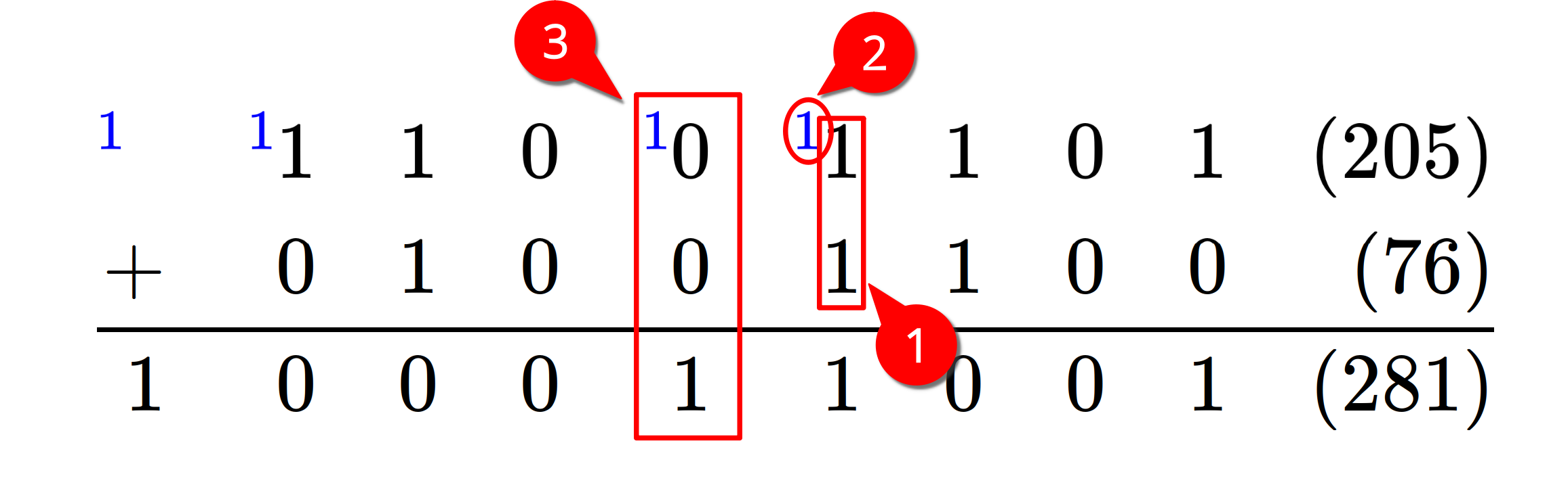
Shown in the above diagram, a half-adder corresponds to the calculation of the input bits to a single column (1). But this doesn’t account for a possible carry-in from the lower column (2). A full-adder is used to calculate the whole result and carry-in for a given column (3). It adds up all three input bits (the two data bits and the carry-in bit) and produces a result bit and a carry-out bit.
To calculate the actual result for a given column, a full-adder needs to
- Add the input bits at that index, and then
- Add the result of the above calculation with the carry-in bit.
Both of these additions only use 1 bit inputs, so we can use our half-adders from the previous section! Specifically, a full-adder can be constructed from two half-adders (and maybe some extra gates). The carry-out of the full-adder is the OR of the carry-outs of the two half-adders.
Why is the carry-out calculated this way? What should happen if both half-adders set their carry-out bits to 1? Is this even possible?
Complete and test full-adder.dig.
We now have a full-adder that can add two bits and a carry-in, and produce a sum and carry-out. To make an
Complete and test a 4 bit adder in ripple-carry-adder.dig.
The piping of each carry-out to the carry-in of the next full-adder gives this circuit the name ‘ripple carry adder’, as the carries propagate through the chain. While it closely resembles how we do the addition manually, the propagation takes a relatively long time (especially when we increase the number of bits). Other more advanced adder designs have been developed to minimise the delay in calculating carries (these are not covered in this course).
Exercise 5: Subtraction#
Our last remaining ALU operation is subtraction. But instead of trying to implement a custom subtraction circuit, let’s think about how subtraction relates to addition. When we subtract a number, it’s the same as negating it first and then adding. That is,
So, how do we negate a binary number? We are using the two’s complement encoding of negative numbers, for which the definition says we:
- invert all the bits (logical NOT), and then
- add 1
(see the resources section for links to where two’s complement is covered in the lectures. If you aren’t sure how it works, take the opportunity during the lab to ask a tutor!)
The inversion is straightforward with NOT gates. Adding 1 is doable now we have an addition circuit, but can we be clever here? When we do a regular addition, what is the first carry input set to? Normally addition doesn’t need it, so we leave it as 0. But if we set it, how does it affect the output?
Well, because it’s the carry into the first index, if it’s set then it will add 1 to the result. And this is exactly what we want! So to perform a subtraction, all we need to do is negate the second input and set the first carry input.
So it turns out our adder is also suitable for subtraction too (with only some minor modifications). To prevent wasting space in our ALU, let’s implement a component that can add or subtract depending on a new input bit. If this input bit is set (1), we should do a subtraction. If it is not set (0), we should do an addition.
Create and test a 4 bit adder-subtracter in adder-subtracter.dig. You may want to use the built-in Adder circuit as a starting point which you can find through Components -> Arithmetic -> Adder. You may also find the multiplexers from last week useful here (this time you may use the built-in multiplexer though).
Building the ALU#
We now have all the calculation components necessary to make our ALU. We just need to put them all together and add our inputs and outputs.
Specifically, our ALU will have three inputs:
- First data input (16 bits)
- Second data input (16 bits)
- Operation selection input (2 bits)
The operation selection input is like a generalisation of the add/subtract selector in the adder-subtracter. It determines what operation is performed on the input data, much like the operator buttons on a calculator. Why is it 2 bits? Because we have 4 operations, we only need 2 bits to pick from the 4 unique choices. If we wanted to add more operations we would need to increase the width of the operation selection input. The operation associated with each selector value is arbitrary, however to let the tests work our ALU will use the following associations:
| Selector | Operation |
|---|---|
| 00 | ADD |
| 01 | SUB |
| 10 | AND |
| 11 | OR |
You may find that an alternative assignment allows a simpler implementation when it comes time to integrate an ALU into your CPU.
We will also have 2 outputs:
- Result (16 bits)
- Flags (4 bits)
The result is simply the result of whatever operation we selected. The flags can be thought of as ‘interesting properties’ of the operation. They will be explained in detail in a later section. For now we can leave them as zero.
Exercise 6: ALU Result#
We’ve covered all the calculation components of the ALU, all that’s left is to decide which one to produce as our result, and calculate the flags.
Calculate and test the RESULT output in alu.dig. Hint: connect the ALUOP input to decide which calculation result to let through as our ALU result.
Like with the bitwise logic operations, Digital provides a built-in adder component under Components -> Arithmetic -> Adder with a configurable bit width. Use one of these as part of a 16 bit adder-subtracter component, instead of the 4 bit one we made in an earlier exercise.
Exercise 7: ALU Flags#
Now we just need to calculate the flags (a ‘flag’ is a common term for a binary value; in our case it means a 1 bit value). These values are intended to provide insight into some properties of the operation. For example, we might have a flag to indicate if an addition operation tried to carry into the 17th bit. As the result output only has 16 bits, this 17th bit would normally be silently discarded. Instead, with the carry flag, we can detect when the result is not ‘correct’ as would normally be expected when adding those inputs on paper.
Well, why don’t we just increase the output width to 17 bits then? We could, but then we couldn’t use the result as an input for another operation. In the context of a full CPU, things work a lot smoother when all our values are the same width. The carry flag is an unobtrusive way of temporarily preserving that 17th bit without affecting the result width.
We will be implementing 4 flags:
- Z (zero)
- N (negative)
- C (carry)
- V (overflow)
In our ALU we represent these flags as bits in the FLAG output. The order is
| 3 | 2 | 1 | 0 |
|---|---|---|---|
| V | C | N | Z |
Zero and Negative#
First determine the zero (Z) and negative (N) flags. These only depend on the result of the ALU.
- The zero flag is set when the result is
0000 0000 0000 0000. - The negative flag is set when the result, viewed as a 16 bit two’s complement signed number, is negative. This means that bit 15 (the ‘leftmost’ or ‘highest’ bit) is set.
Calculate and test the zero (Z) and negative (N) flags in the FLAG output. Recall that Digital provides wire splitters to support splitting and combining individual wires.
Carry#
Next determine the carry (C) flag. This is set when the addition of the two inputs resulted in a carry into the 17th bit (this includes the subtraction operation too; once we negate the second input, it can be viewed as an addition). If the operation was AND or OR, the carry flag is set to 0.
Calculate and test the carry (C) flag in the FLAG output. You may find this has already been calculated somewhere already. Feel free to add new outputs to existing components if it helps.
Overflow#
Finally, the overflow (V) flag is semantically set when the result of an addition wraps past either end of the signed number range (much like carry is set when addition wraps past the end of the unsigned number range). This can be detected by checking if the inputs (viewed as signed two’s complement values) have the same sign, but the result has the opposite sign. E.g.,
As with the carry bit calculation, a subtraction operation can be reinterpreted as an addition after negating the second input. So for subtraction the overflow rule above applies after inverting the sign of the second input.
If the operation was AND or OR, the overflow flag is set to 0.
Calculate and test the overflow (V) flag and pass it through to the FLAG output. You may want to draw up a truth table of the signs of the inputs, the operation (add / sub), and the sign of the result to help with developing a circuit.
Is it possible for all of the flags to be simultaneously on? If yes, give an example. If not, why not?
Conclusion#
Congratulations! You have now built a fully functional ALU. Based on just the operation selection signal it can perform a variety of computations on the input data values. Next week we will be looking at storing state, such that we can read our input values from there and write our result back to it.
Don’t forget to commit and push your work in this lab