Overview#
The assembler is implemented as a VS Code extension, which you should already have downloaded and installed. If this is not the case, visit the software setup page. To use the assembler, open the folder containing your quac.json file and assembly programs in VS Code. Ensure your CPU is open in Digital. Right-Click your pc register and mark it as a program counter. The first time you run the assembler, you will need to create a debug configuration, using the ‘QuAC ISA’ option. Run the debugger with the start debugging button, or press F5. The assembly code can be stepped through as in a normal debugger, and the CPU will run in lock-step in the Digital window. The CPU can also be run purely in Digital, by using the assembled program without the debugger. Start and stop the debugger. In your CPU’s circuit specific settings, set it to pre-load program memory at start-up with the file program.bin.
Step-by-Step#
Follow these steps to set up the assembler and debugger in a project.
-
Open your CPU in Digital.
-
Mark your
pcregister as a program counter.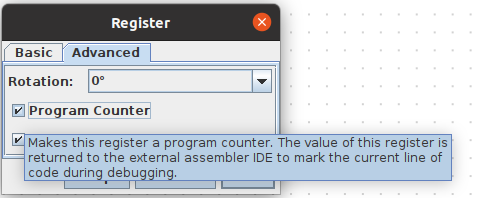
-
Open a folder containing your
quac.jsonfile in VS Code. You can find a copy of this here. Create a.asmfile for writing your program — you can call itprogram.asmor similar. Note that.asmis the extension recognized by the assembler. Write some assembly! -
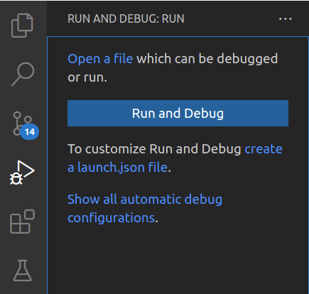
In the debug pane, click ‘create a launch.json file’.
-
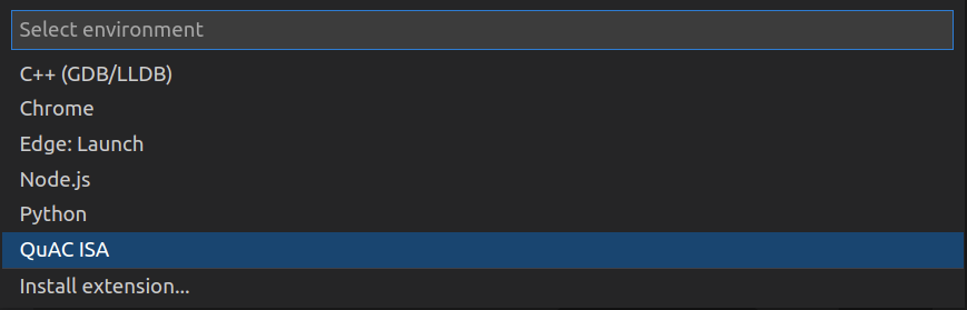
Select QuAC ISA.
-
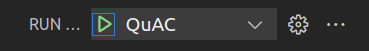
Run the Debugger by clicking the green arrow.
-
The debugger should now be running. The CPU in Digital will update in lockstep with the debugger. Use the step over button or F10 to run each instruction.

-
Stop the debugger with the red stop button. Mouse over an instruction in your assembly file — a pop up window should appear with details about the instruction.
To run the program without using the debugger, set Digital to load the program file (program.bin) in to
RAM at the start of the simulation. Make sure ‘Preload program memory at startup.’ is ticked!

Custom Instructions#
Part of assignment 1 is to write a couple of programs demonstrating your extension. To facilitate arbitrary extensions, the assembler gets it’s syntax to machine code rules from the quac.json config file.
The config is very general, but can’t satisfy every possible design. If you need capabilities beyond what is currently supported, you can ask about it on the forum and we can look into it. However you do not need to wait for any support to be implemented; you can always manually assemble your new instructions and put them in with the .word directive (like in lab 7 exercise 2, not released yet). Just put a comment on the line with the intended assembly syntax for the instruction. E.g.,
.word 0x1234 ; foo r1, 0xFEDC (custom expansion from 8 bits in the instruction to 16 bit number)
JSON#
JSON is a simple and stable structured data format. It supports null values (like None in Python), booleans, numbers, strings, arrays (like lists in Python), and objects (like dictionaries / maps in Python). If you did the 1730 prerequisite then you should be familiar with these data types (in fact, JSON is very similar to just using Python dicts & lists). If you did the 1100 prerequisite then you might not have seen objects: these are mappings of strings (called ‘keys’) to arbitrary values. E.g.,
{
  "key1": 5,
  "otherKey": "foo"
}
This is an object that associates the string "key1" to the number value 5, and the string "otherKey" to the string value "foo"
The most common JSON error is missing / extra commas. JSON is very particular about comma separating entries in an object or array, and no trailing comma. VS Code should underline any such errors with a red squiggle for easy identification.
For its use in the course, while you can look over the specification (it’s very short, and there are numerous guides / blogs out there about it), you can get by fine just by mimicking what’s already in there (the base specification). New instructions are added to the "instructions" object. The key is a unique name for the instruction, and the value is an object defining
- the syntax (what you write),
- the machine code (what it assembles to), and
- various optional info entries.
Hovering over any component should also make a popup with a description of its purpose.
Syntax#
The "syntax" property declares how an instruction can be written in an assembly program.
Specification#
The instruction syntax follows several rules:
- The first part must be a name, such as
ADD. - This name may optionally be followed by a
?. This allows a condition suffix to be added when using the instruction (soaddandaddzwould both be accepted). - Whitespace is ignored
- The rest is a sequence of
-
literal punctuation (
,,[, and]). This is matched exactly against each use of the instruction. -
variables declared with the form
<NAME:TYPE>, where the<,:, and>are written literally, and theNAMEandTYPEare replaced with the name of the variable (usable in the machine code section) and the type of the variable. -
optional sections declared with the form
{ ... }, where the{and}are literal and the...is more literals & variables. Optional sections may be omitted in the assembly statement. Any variables inside an optional section must declare a non-optional default value (raw binary1s and0s, or another variable name). This default value is used if the optional section is not present in a given assembly statement. The syntax for adding a default value is to insert?VALUEafter the type; e.g.,<RB:reg?000>to declare a variableRBthat is a register that defaults to000(rz).
-
literal punctuation (
There are four variable types:
-
reg: A register index. The syntax accepts register names (r1,pc, etc.) and uses the corresponding 3 bit index value in the machine code. -
uintN: AnNbit unsigned (0 or positive) number. E.g.,uint8allows values from -
sintN: AnNbit signed number (2’s complement). E.g.,sint8allows values from -
xintN: AnNbit signed or unsigned number. E.g.,xint8allows values from
Examples#
-
JP <NUM:xint8>-
NUMis declared to refer to a signed or unsigned 8 bit number. - This syntax definition accepts assembly statements such as
  jp 0
  jp -12
  jp 255
but rejects assembly such as
  jp r4   ; 'r4' is a register, not a number
  jpz r3  ; no condition suffix allowed
  jp 256  ; number out of 8 bit range
-
-
ADD? { <RD:reg?RA> , } <RA:reg> , <RB:reg>- This can be thought of as two separate syntax definitions:
-
ADD? <RD:reg> , <RA:reg> , <RB:reg>, and ADD? <RA:reg> , <RB:reg>
-
-
?marks this as accepting condition suffixes on theADD -
RDis declared to refer to a register, and defaults toRAif only two registers are given - This syntax definition accepts assembly statements such as
  add r1, r2, r3   ; RD=r1, RA=r2, RB=r3
  add r1, r2       ; RD=r1, RA=r1, RB=r2
  addz pc, r4, rz  ; RD=pc, RA=r4, RB=rz
  addz pc, rz      ; RD=pc, RA=pc, RB=rz
but rejects assembly statements such as
  add r1 r2  ; missing the comma between the registers
  add r2, 5  ; '5' is not a register name
  add { r4 , } r3, r2  ; the {} are not part of the program syntax!
- This can be thought of as two separate syntax definitions:
Machine#
The "machine" property declares how a matched instruction is to be encoded into machine code.
Specification#
- Whitespace is ignored (except to separate words; i.e., distinguish between
foobarandfoo bar). -
0s and1s are encoded literally - Variable names can be used. These will be substituted with bits corresponding to the actual value used in a given assembly statement. The width (number of bits) of a variable is determined by its type (see the ‘syntax’ rules).
- A special variable
Cis available if the instruction syntax allows condition suffixes (marked with?). This variableCresolves to a 1 bit value:0if a suffix is not added, and1if thezsuffix is added. - After all components are resolved to
0s and1s, the bits are all concatenated together into a 16 bit value.
Examples#
Consider the following:
- Syntax
ADD? { <RD:reg?RA> , } <RA:reg> , <RB:reg>from before - Machine config
1000 C RD 0 RA 0 RB - Assembly statment
addz pc, r3
We can resolve this like so:
- It starts with the bits
1000because they are always part of this machine config - Next is the bit
1because we wroteaddz, so the variableCresolves to1 - Next is the bits
111becauseRDdefaults to theRAvalue, which is the registerpc. Elsewhere in the config we declarepcto ber7, which the assembler knows to have encoding111. - Next is
0because it’s a literal part of this machine code config. - Next is
111becauseRAis the registerpc, which we declared isr7, which the assembler knows is111. - Next is
0because it’s a literal part of this machine code config. - Next is
011becauseRBis the registerr3, which the assembler knows is011.
All-in-all we have resolved each part to raw 0s and 1s, ending up with the final encoding 0b1000 1111 0111 0011 or 0x8F73.
Semantic / Description / Other#
The other sections are all optional and provide human readable documentation about the instruction. There is no fixed syntax for these entries. They just get copied directly into the hover message when you are writing the program.
Debugger Usage Tips#
- The yellow line highlights the instruction about to be executed. You should be able to see the circuit ready to execute this instruction over in Digital.
- The variables view will highlight values that changed since the previous step.
- Click just to the left of the line number to set a breakpoint (a red dot) on that line. Clicking the ‘continue’ (green triangle) button in the debug buttons will run your program until the PC reaches an instruction with a breakpoint on it. You can add as many breakpoints as you like. Click the red dot to remove that breakpoint.
- Set measurement values in your circuit files to have them appear in the variables list in the debugger. Registers are listed separately from all other measurement values.
- Right-Click a variable value in the debug pane to pick how to represent it (binary, decimal, or hexadecimal).
Troubleshooting#
There are several things that can go wrong with the assembler and Digital, and some aren’t easy to detect. Here’s a list of common issues and things to check for when something goes wrong. More may be added as it gets widely used. Don’t forget to make sure your extension is up to date before trying to troubleshoot an issue: an update may have already resolved it!
Cannot Locate Config#
This happens when the quac.json file cannot be found. The assembler will look in every directory between the current file and the open folder in VS Code. Make sure you have a quac.json file somewhere in there. When in doubt, put it in the same folder as the assembly program file.
Failed to Deserialize Config#
This happens when there’s an error in the quac.json config file. Open it up and check for any yellow or red underline squiggles. Fix those up before trying again.
Failed to Assemble Program#
This happens when the assembler doesn’t know how to turn your program into machine code. First look for red underline squiggles in the file: these must all be fixed before it will work. If it still fails to assemble, then check the error message closely. Most of them will give a general reason for failure and a line number to focus on.
Unrecognised instruction means that none of the instruction patterns declared in the config match the current statement. Often this is because you are missing a comma.
Failed to Connect to Digital#
This happens when the debugger can’t talk to Digital. Most likely you haven’t opened Digital yet. If your Digital version is v0.30 or greater then you may also have to enable “Allow remote connection” in settings with port value 41114.
If this does not work, then restarting your computer may help.
Missing Variables#
This happens when you haven’t set anything as measurement values. The VS Code variables will only show what Digital would show in its measurement table. If neither are showing your registers (and maybe other measurement values) then you need to configure them to be shown in your circuit.
Failed to Step Simulation#
If the debugger doesn’t seem to be stepping through your program, check if there’s an error popup saying “Failed to step simulation” or similar. This indicates a communication error with Digital. Common causes are
- Circuit is invalid. Check Digital for any error popups and fix accordingly.
- No program memory. There must be a RAM component configured as “Program Memory” (Right-Click RAM -> Advanced tab) in the simulator.
- No program counter / too many program counters. Make sure there is exactly one register marked as the program counter in the simulator.
- No clock / too many clocks. Make sure there is exactly one clock component in the top level CPU. Clocks in subcircuits (circuits imported into your CPU) are fine.
- Simulation ended on Digital side. You’ll have to restart debugging if you want to run it again.
Rarely, an old Digital process may stick around and occupy the communication channel used by the debugger. This can cause strange errors. If it happens, Digital should say something like “Can’t connect because port is in use” in the bottom bar. Resolve this by killing the old Digital process (restarting your computer will work if you don’t have any other way to do so).