Lab 4
In this lab, you will use OpenGL and JOGL to create a series of 3D scenes of increasing complexity.
We intend for you to use the OpenGL 1.1 fixed function pipeline for each question. However, you are free to implement all three tasks using shaders if you wish. Using shaders to solve these problems will likely be more difficult, but at the same time would provide a useful starting point for your second assignment.
For each task, we provide a reference video and image. Please refer to these for specifics about how each scene should look. Your solutions should closely match the references provided.
Source files for this lab can be found here.
Note: the supplied code for each task is identical. In each case, you will need to modify it to complete the task. As there is quite a bit of overlap, you might find it helpful to copy and paste some of your solutions from one task to the next.
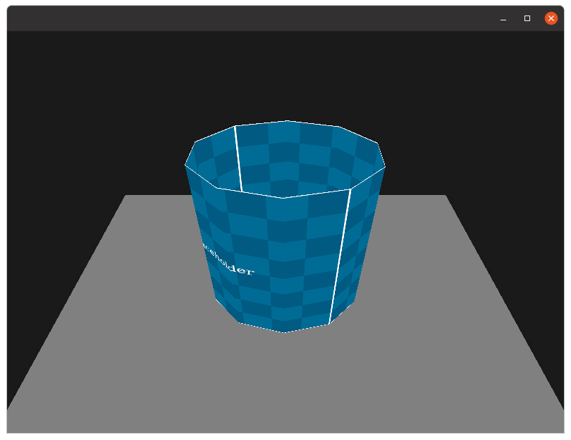
Task 1 - Texture Mapped Cylinder
Using OpenGL, construct an open cylinder with ten rectangular sides. Have the cylinder rotate slowly on its y-axis. Include a plain gray floor and a dark gray background. No lighting should be used. The cylinder should be texture mapped using cylindrical texture mapping where the texture wraps around the cylinder’s circumference exactly twice, and length exactly once (as depicted in the video). The texture should also be oriented so that the ‘placeholder’ text is the right way up, and not reversed. The cylinder should be centered at the origin, and be of height 150 units, and radius 50 units.
Implement a camera and have it pan over the object as follows:
- the camera should always be looking at the origin,
- the camera’s position should be \((x,y,z) = (0, 200, 350 + 200 * \sin(\theta))\),
- the camera’s up direction should be the y-axis,
where \(\theta\) increments slowly over time.
The required animation, and texture mapping is depicted in the reference video. Note that the white edge of the texture should be visibile at the top and bottom.
Hint 1: GLU has a helpful command gluLookAt which can be used to achieve the camera panning.
Hint 2: There are two sensible ways to solve this. The first way involves carefully positioning quads such that they form a cylinder. If you do this, you might have use some high school trigonometry to get the locations correct. The alternative method is to generate the vertices all in one go and have the primitives reuse them. This method is slightly more efficient and means that the sides will never overlap/there will never be any holes. Either solution is fine, so long as it renders correctly with no gaps or overlap.
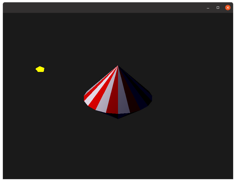
Task 2 - Basic Lighting
Using OpenGL, create a “spinning-top” that is made up of 20 triangular segments for the top, and 20 triangular segments for the bottom. The colour of these sides should alternate between red and white as depicted in the example image. The top should be stationary and not spin. The top should have a radius of 50 units and a total height of 150 units. Include a dark gray background.
Your scene should be lit with a vertex-based Gouraud shading lighting model for the spinning top. Have a single light, which is a point light positioned at
\[(x, y, z) = 100 * (\sin(\theta), \sin(\theta/3), \cos(\theta)))\]where \(\theta\) increments slowly over time.
This lighting model should include ambient and diffuse light but no specular lighting. A small bright yellow sphere should be drawn at the point-light’s location. Also, each face should have constant normals, that is, do not interpolate normals over the surface. The final result should match our reference video.
[4-Oct-22] Clarification - The default lighting model for OpenGL is Gouraud shading, so if you solve this problem using the built-in lighting model, there is no need to implement the lighting model. Instead, you only need to define the lighting and material properties and set up the model’s normals. See Week-8 notes, slides 14,15,16.
To help you get started I’ve also included some code below that calculates an (unnormalised) normal given three input vertexes. In this particular code fragment I assume vertexes are given in counter-clockwise order.
double v1x = x2-x1;
double v1y = y2-y1;
double v1z = z2-z1;

double v2x = x3-x1;
double v2y = y3-y1;
double v2z = z3-z1;

double nx = v1y*v2z - v1z*v2y;
double ny = v1z*v2x - v1x*v2z;
double nz = v1x*v2y - v1y*v2x;
Hint 1: A good way to check that your lighting model is correct is to replace the spinning top with glut.glutSolidSphere. It should be obvious if your lighting model is correct using this built-in object.
Hint 2: You will want to disable lighting when you draw the small yellow sphere.
Hint 3: Getting the normals correct can be difficult. You might want to enable GL_NORMALIZE, and also note that using non-uniform scaling will distort your normals.
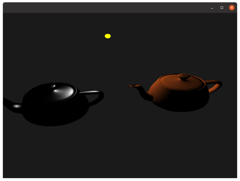
Task 3 - Working with Materials
In this task we are going to make use of the full Phong lighting model, and experiment with some materials.
We will be using the built in teapot model, which can be created using
glut.glutSolidTeapot(50);
Create two copies of the teapot, spaced 100 units from the origin along the x-axis. Define a single point-light at location \((x,y,z) = (0, 100, 100)\) with the following properties
- Ambient (0, 0, 0)
- Diffuse (1, 1, 1)
- Specular (1, 1, 1)
On the first teapot we will simulate a ‘clay pot’ material, using the following properties:
- Ambient (0, 0, 0)
- Diffuse (0.7, 0.3, 0.1)
- Specular (0, 0, 0)
The second teapot simulates a ‘metal pot’, and should use the following material properties
- Ambient (0, 0, 0)
- Diffuse (0, 0, 0)
- Specular (1, 1, 1)
- Shininess 50
All objects in this scene remain static, except for the camera, which should rotate around the origin with the following coordinates \((x,y,z) = (250 * \sin(\theta), 200, 250 * \cos(\theta))\)
As the camera rotates you should be able to observe the lights reflection moving across the second pot (but not the first). The final result should match our reference video.
Bonus Task - Procedural Geometry
As always, I have included a bonus task. In the last lab, we looked into procedural textures. In this lab, we will look into procedural geometry. Your task is to create a procedural object generator that creates objects based on input parameters. Examples could include
- A cylinder, as in task-1, with height, the number of radial and length divisions, a radius, and an option to cap the cylinder.
- A sphere, with x number of slices, and y number of stacks, as well as a radius (similar to GLUT’s one).
- A plane, with x by y number of tiles.
In each case, the object should be generated with a configurable number of divisions, and UV coordinates should be generated using an appropriate UV mapping system. (Note: no matter how you do it, a capped cylinder is going to have distorted UV cords for the caps)
Also, question: Why would we want subdivisions on a flat plane? When would this make sense?