Even though Digital is a visual language and different from the text-based languages you’ve written in up until now, complexity builds up in much the same way as in programs and it is a struggle to keep your circuits neat. In other courses you may have learnt coding style, like naming your variables well and adding comments. The following will describe a similar thing, except for Digital.
Have your wires move in a consistent direction#
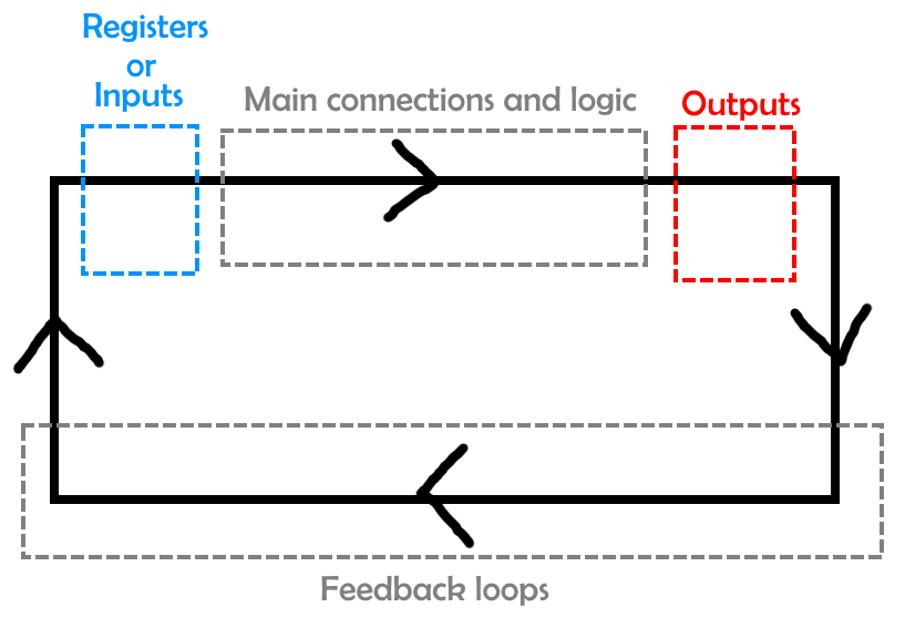
In general, you want wires to flow downwards and to the right. To achieve this, start with your inputs on the top and on the left side of your circuit, and outputs in the bottom and right sides.
The introduction of sequential circuits will require you to add feedback loops, which will force you to add some wires that flow backwards. Try to add these loops underneath the rest of your circuitry so the wires form a clockwise loop, which is easy to understand visually. This might look something like:
Minimise bends#
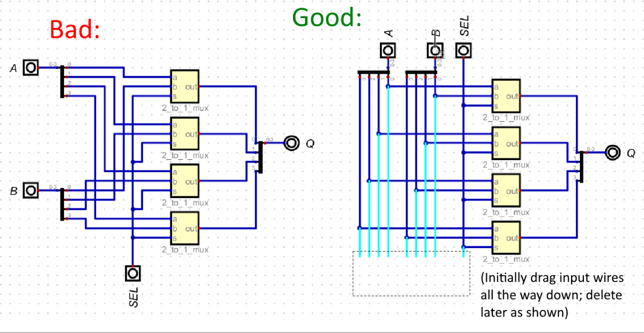
If you start out just connecting wires however you can, you will find that because you cannot overlap two wires in parallel, you will have to dodge around your existing wires. This can lead to a huge mess and make it difficult to follow where wires go. One simple trick to counteract this is start by rotating your inputs to point downwards and drawing wires down from each one. Then, to connect an input to something else, draw a horizontal wire from its vertical line to where you want to connect. This makes sure (in the ideal case) that there is exactly one bend in the connection from each input to something else, which makes everything neater.
An example of this using the 2 to 1 wide multiplexer is shown below. In the first case, we have just tried to connect the wires however possible, and in the second case we used the trick described. Note, as explained in the diagram, that it is easy to delete the loose ends of the vertical wires you drew at the beginning once you’re done.
Avoid diagonal wires#
You may discover that the D key allows you to draw wires diagonally. This is generally not recommended, as wires going in different angles adds a lot of visual noise. There are a few rare exceptions though, such as the feedback loops in the SR latch from lab 3.
Use tunnels, but wisely#
Tunnels are a component that you can find under Components > Wires > Tunnel, which act as if they are connected by invisible wires
(which are presumably underground, hence the word “tunnel”). This can be useful especially when there is a single component that has to connect to many places in your circuit and you want to avoid wires going everywhere, like the control signals in your CPU or the clock signal introduced in lab 3.
However, tunnels can also obscure your circuit by making it difficult to tell where a particular connection is coming from or going to, and what components are connected to what other components. So be careful and don’t use too many! If your wires are getting messy, try other ways of solving it like spacing things out more and moving around components.
Use labels#
Like comments in text based languages, Digital has something called labels, which you can find as Components > Misc. > Decoration > Text. These act like text boxes you might use in Powerpoint, which allow you to label things. This can be useful to indicate what value is going through a particular wire and other information.
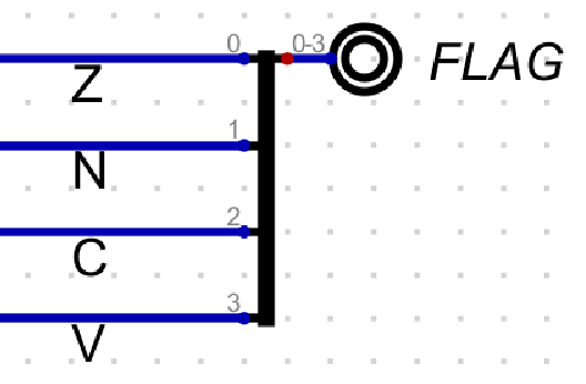
For instance, the below example shows how you can label the different bits of the ALU FLAGS output to indicate which flag each bit corresponds to.
Avoid (serious) inefficiencies#
Another aspect that we will mark as part of style is the efficiency of your circuit. Are there places where you could have avoided using a component? Do you have unnecessary logic? You don’t have to go too far and use the bare minimum logic possible, but try to take some simple steps.
Note that there may be tips in the lab manuals on how you can do certain things more efficiently. If you’re unsure, you can go back and read them!
Examples where you could be more efficient:
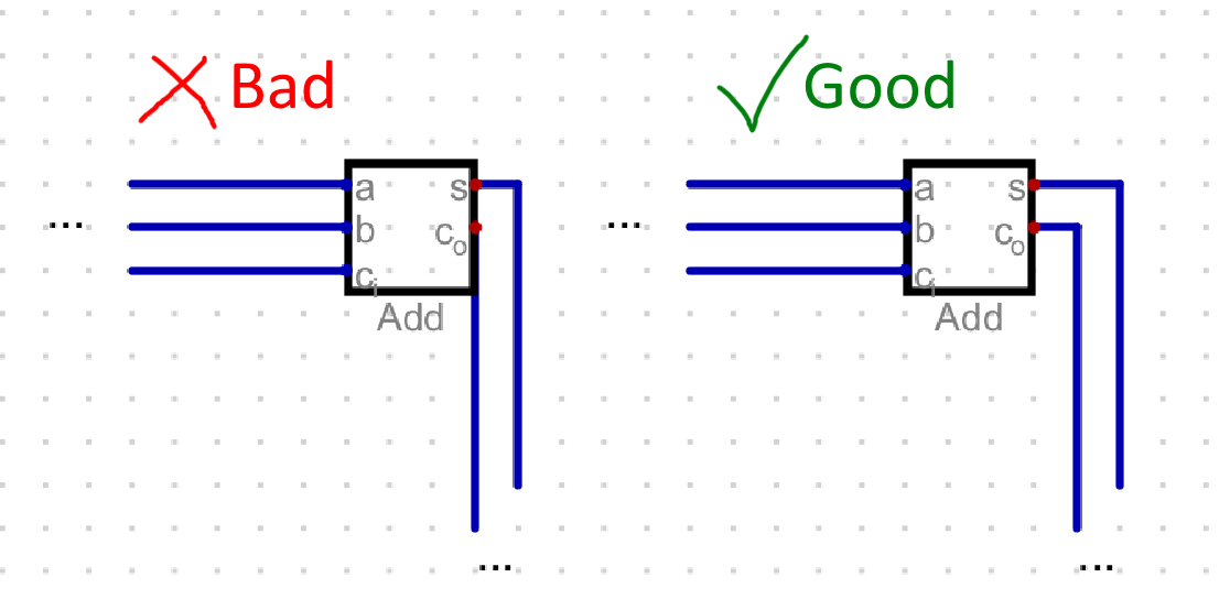
- Using a single
N-bit gate rather thanNseparate 1-bit gates where appropriate. In the following example, using a single 2-bitANDgate functions identically without taking up as much space. This is especially important for any adder components you use for e.g. exercise
2 and 3.
This is especially important for any adder components you use for e.g. exercise
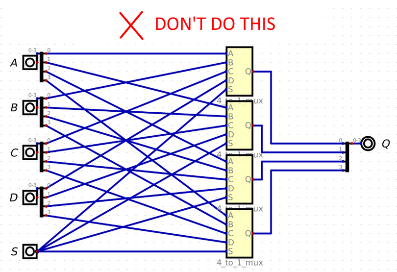
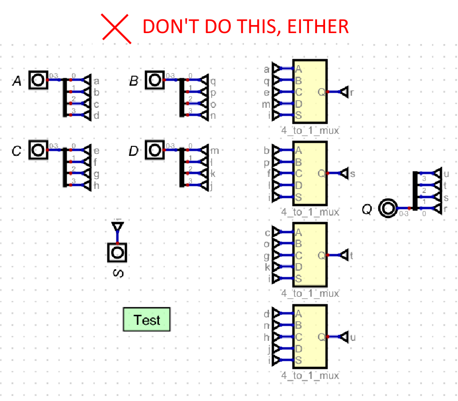
2 and 3. - Using multiplexers with redundant cases. For example, if you only need to select between 4 different inputs you should not use an 8-to-1 multiplexer.
- Using multiplexers with only/mostly constant components where a logic gate
would suffice. For example:

There’s also a specific example in Lab 2 (and the Checkpoint) where you can use a single adder for both addition and subtraction instead of two adders.
There are cases where making your circuit more efficient can cause it to become harder to understand. These are usually tricky optimisations so it is up to you whether to pursue them, but if you do, you will still have to make sure your resultant circuit is understandable. Labels can be a good tool in this case since you can explain a bit about how your optimisation works, with annotations on parts of your circuit or in a note to the side of your circuit.
Other tips#
- Try not to have wires overlap with the edges of components, as below
-
Try to make your circuit well spaced out. You may be tempted to try and cram it all into as little space as possible, but this usually harms readability.
-
Check out the Tips and Tricks page to see what you can do with Digital components to make your life easier.
Is my circuit neat?#
The ultimate test for whether your circuit is neat is whether you can still understand it after not looking at it for a bit. Make sure to leave a little time to review your circuit before the deadline, and if you find something confusing that you wrote ages ago, you know what to fix!