Outline
In this lab you will:
- revisit some concepts in 3D
- discuss your interpretation of the theme and your goals for the artefact
- create a rough blueprint for your artefact
- start “sketching” the blueprint of your artefact with code
Introduction
Welcome back! This week, we will continue to develop your ideas for your project and start sketching those ideas with code.
Part 1: 3D World Building
We will go back and look at some concepts we have only briefly touched upon in creating 3D graphics with p5.js.
do: Fork and clone the week 12 template repo. It contains a sketch we will modify to create 3D geometry from scratch.
Tetrahedrons
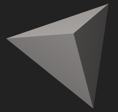 A tetrahedron is a platonic solid — also known as triangular pyramid — is the simplest 3D solid shape.
It has 4 triangular faces, 4 vertices, 4 normal vectors, 6 straight edges. In a regular tetrahedron, the faces are all identical equilateral triangles. You can read more about them here.
A tetrahedron is a platonic solid — also known as triangular pyramid — is the simplest 3D solid shape.
It has 4 triangular faces, 4 vertices, 4 normal vectors, 6 straight edges. In a regular tetrahedron, the faces are all identical equilateral triangles. You can read more about them here.
The sketch contains code to create a tetrahedron.
It does this through creating 4 faces. Each face has 3 vertices, but the vertices are shared.
Faces are created thus:
    beginShape();
    vertex(x1,y1,z1);
    vertex(x2,y2,z2);
    vertex(x3,y3,z3);
    endShape(CLOSE);
Where:
beginShape()informs the program to expect code following to specify vertices for faces for shapes.(x1,y1,z1)are the coordinates of the first vertex, etc.endShape(CLOSE)informs the graphics renderer that all vertices have been specified.CLOSEmeans the vertices are closed into a complete face.
We create 4 faces using the 4 vertices of the shape repeated appropriately. This tells the graphics renderer to draw 4 faces which will have shared vertices and edges.
Surface Normals
In order for the object to render correctly with lighting (beyond ambient lighting), we need to tell the graphics renderer which way the faces “face”. That is: how they are oriented in 3D space. We use a normal vector to do this. A normal vector points “out” from each face. Read more about surface normals here.
We need to calculate normal vectors for each face and tell the renderer to use these vectors when rendering.
We can do so like this:
    beginShape();
    normal(nv);
    vertex(x1,y1,z1);
    vertex(x2,y2,z2);
    vertex(x3,y3,z3);
    endShape(CLOSE);
Where nv is the normal vector, and normal(v) asks the renderer to use the supplied vector as the normal. You can manipulate normals to create unexpected output.
Texture Coordinates
Suppose we want to put an image (or video, or sophisticated texture using a shader) onto our shape. We have specified that our shape has 4 faces, but we have not specified “which side is up” for each face. Imagine you have to include instructions for a painter or printer to illustrate each side, how should each side be oriented as it is painted? How should images be scaled or rotated to fit on a face? This is the job of texture coordinates. Read more about texture coordinates here.
2D surfaces (the “planes” of our 3D surface) have texture coordinates specified using a (u,v) mapping. Texture coordinate space can be relative to scale, or scale independent. p5.js calls this “IMAGE”-based or “NORMAL”-based. For “NORMAL” we have a coordinate system which ranges from (0,0) to (1,1).
When defining our faces, we need to include texture coordinates as follows:
    beginShape();
    normal(nv);
    vertex(x1,y1,z1, u1, v1);
    vertex(x2,y2,z2, u2, v2);
    vertex(x3,y3,z3, u3, v3);
    endShape(CLOSE);
Where (u1,v1) define where this vertex fits into the coordinate space (0,0) to (1,1). Often we wil use the values (0,0), (0,1), (1,0) and (1,1) for square or rectangular surfaces.
To put the texture onto the surface we need to:
- preload the image
- apply the image as a texture, and
- define the texture mode
You should also create some lights, and disable normalMaterial.
Part 2: Revisiting your interpretation
When you left class last week, you will have written down your interpretation of the theme for the first portfolio theme: “A Better World”. You will have also identified some goals for the design of your user experience or performance. During this first activity, your instructor will make their way around the classroom. This is an opportunity for you to discuss your interpretation of the theme and goals for the artefact with your instructor and get some feedback.
do: Open your template repo from last week so you can easily reference it when speaking to your instructor.
Once you’ve discussed your ideas with an instructor, do the following.
do: Ensure that you have forked and cloned the portfolio template repo. We will be using this repository throughout the weeks of developing your response to this provocation. You will find an portfolio.pptx and portfolio-entry-1.md file with slides/headings for the remaining weeks of this course. You can use whichever file format you prefer. Make of copy of portfolio-entry-1.md, or of the equivalent slide in portfolio.pptx. In the new file/slide: 1) restate your interpretation of the theme and 2) restate your goals for the user’s experience or the performance.
Part 3: Describing your blueprint
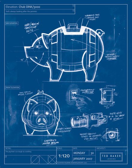
Once you have completed Part 1, you can move on to creating a hand-drawn blueprint of your artefact. What do we mean by “blueprint”? The blueprint of your artefact should capture the essential function(s)/components of your artefact and omit the details relating to the visuals/sounds/interactions. Spend some time thinking about what you want to communicate to an audience member experiencing your artefact.
talk: What are the essential functions/components your artefact should have to communicate your interpretation of the theme to the audience? Discuss your ideas with an instructor.
Once you have a better idea of what these essential functions/components are, draw a rough sketch of the blueprint for your artefact by hand. This doesn’t have to be polished — we just want a rough outline of what the essential parts of your artefact might look like.
do: Take a picture of your hand-drawn blueprint and add it to the portfolio file in your template repo under the Week 12 section. Ask you instructors if you need help with this. Commit and push your work to git.
Part 4: Sketching your blueprint
talk: Share your blueprint with your instructor — they’ll be making their way around the class. Your instructor will provide suggestions on how to translate your blueprint to code.
You are going to use the rest of the lab to start sketching your blueprint with code. Since we won’t be capturing the details of your artefact, we recommend implementing the essential functions/components of your artefact using simple shapes.
do: That’s all for this week’s class. Be sure to commit and push your work to git.
Summary
Congratulations! In this lab you:
- revisited, rediscovered, or explored in greater depth some concepts in 3D
- discussed your interpretation of the theme and your goals for the artefact
- created a rough blueprint for your artefact
- started “sketching” the blueprint of your artefact with code