Outline
In this lab you will:
- learn about creating composite 3D objects in p5.js
- investigate image-based texture mapping
- begin implementing your blueprint for this project portfolio item.
Introduction
Week 13 - time is flying by.
This week we will create composite 3D objects and explore the capabilities and limitations of these models. We will also investigate using image-based coordinates for texturing objects, and using multiple textures.
After this, you will continue working on project work.
Do: Fork and clone the week 13 template repo. It contains a sketch we will modify to create composite 3D geometry.
Composite Objects
p5.js enable you to create composite 3D objects from multiple “simple” objects.
A composite object is literally that: an object which includes multiple sources of 3D geometry.
The example pages display an arrow created from a cone and a cylinder (neat).
The function used to create a composite object is buildGeometry()
buildGeometry() takes one (and only one) parameter, which is the name of a function.
The function should “build the geometry”. The function parameter does not need to return the geometry as an object.
buildGeometry() returns a value - which is a 3D model which includes all geometry created in the function parameter.
The returned 3D model has not been rendered, yet.
You can create the model in the setup function (but you might also not want to do this - it depends on what you want the model to be capable of).
To render the model, you call the function model().
For example:
let myModel;

function setup() {
    createCanvas(400,400,WEBGL);
    myModel = buildGeometry(compositeObject);
}

function draw() {
    // black background
    background(0);
    // standard lights, orbitcontrol and a normal material
    lights();
    orbitControl();
    normalMaterial();
    push();
    rotateY(frameCount * 0.01); // give it a spin

    // draw the model
    model(myModel);
    pop();
}

function compositeObject() {
    cube(100,100,100);
}
In the example code, the variable myModel holds the model, the model is “assembled” by buildGeometry(compositeObject), and the model is rendered by model(myModel).
compositeObject is the function parameter to buildGeometry(). We only pass the name of the function.
compositeObject does not return a value.
It contains instructions to render the object. We can add as many object generating statements as we require.
Note: you will need to position and orient all objects relative to each other. Do not think about the object in world space, but each in its own local space. You can move objects relative to (0,0,0) (the object centre) using translate(), and orient objects using rotateX(), rotateY() and rotateZ() (or use quaternions for rotation if you like - this was covered in Week 2).
Think: Can the transformations applied to objects within a composite object change over time relative to each other or is the object a static relic once created? Sure - you can move the object prior to rendering (as seen in the line rotateY(frameCount * 0.01); // give it a spin in the example above), but could you have multiple spheres orbiting our cube independent of this? Hint: you may need to create the object on each draw cycle if you want to achieve this.
Do: Use the supplied template sketch to create a 3D composite object using objects of your choice. You can create any geometry you desire. As an extension you could think about making objects move relative to each other over time (rotations/translations applied using frameCount in determining position/orientation). What limitations have you encountered? What sparks joy?
Think: Where else have we seen the model() function used? Does this spark any ideas for composing objects?
Composite objects introduce the concept of object coordinate space and world coordinate space. You can apply transformations to an object when creating the object, without needing to think about how and where it will be positioned and oriented when rendered.
Think: How might you use 3D composite objects in creating your response to the provocation A Better World?
Image Textures
We have already seen and used image based textures. Last week we looked at NORMAL image coordinates, where the coordinate systems for the (u,v) texture space vary between 0 (minimum) and 1 (maximum). This week we will look at using image coordinates, and how and why we would use these.
Image based coordinates for texture mapping
Image based coordinate mapping systems use the pixel coordinates of the image to be rendered on a surface. In this weeks template, the texture uses IMAGE coordinates.
To specify that you want to use image coordinates, you use the textureMode function as follows:
textureMode(IMAGE); // using IMAGE based coordinates
If you create your own custom geometry (as we did for the tetrahedron last week), then you can specify the texture coordinates to use for each face. This enable you to select specific parts of an image to render on each face.
This capability allows 2 strategies:
- You can create the net of an object (or *unwrap an object to map to 2D) and specify how this maps to faces of an object
- You can create a single image containing separate imagery for every object in you scene.
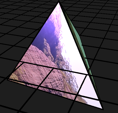
We have used a separate strategy in this weeks template. Specific parts of the image were chosen (seemingly at random) to highlight the capabilities of mapping faces separately.
The template image is 'assets/DSC04206.JPG'. The pixel dimensions of this very large image are: 5472 by 3648 pixels. We can select parts of this image by specifying coordinates such as (1640, 2370). We need to select coordinates for each vertex of our face.
This has been done for our tetrahedron. Here is the mapping for one face:
    vertex(vertices[0].x, vertices[0].y, vertices[0].z, 1190, 256);
    vertex(vertices[1].x, vertices[1].y, vertices[1].z, 190, 1856);
    vertex(vertices[2].x, vertices[2].y, vertices[2].z, 2190, 1856);
This maps the section below to that face:
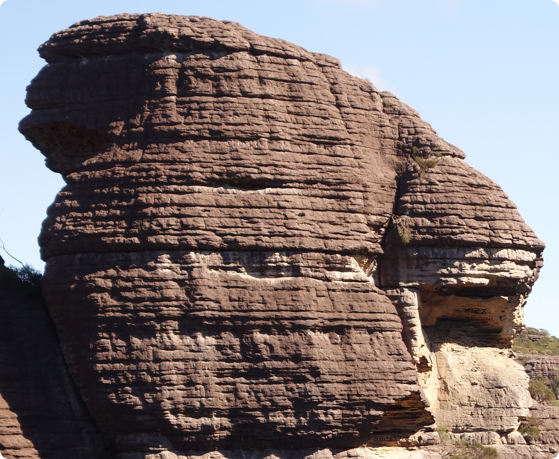
Each face has its own mapping to a subsection of the single image loaded during preload(). These strategies have been used to improve performance in computer games.
Multiple textures
One additional strategy employed in this weeks lab is the use of both textures:
    texture(img); // create the texture
    textureMode(IMAGE); // using IMAGE based coordinates
and materials:
    specularMaterial(130, 160, 200); // create a shiny material with a colour
    shininess(8); // define the level of glossiness of the material
to create our world. This enables us to add shininess and additional colour to our world.
Think: How might you use images and textures in creating your response to the provocation A Better World?
Working Sketches
It is high time that we start working on implementing our blueprints!
What we did last week
Last week we worked on making a rough blueprint of what your prototype/final project might look like. This week, we are going to make a start at implementing some component of your blueprint; whether it be laying down the ‘foundation’ code or implementing a small feature.
What we will do in the coming weeks
There are 3 weeks left, including this week, until you submit your response to the provocation: A Better World. The more ideas you implement (test out), the richer the material you will have to draw on when refining your installation for the creative code exhibition.
Making the most of the classes to come
Creating a refined piece of art or software requires making lots of iterations of your ideas because:
- you wont have a good sense of how your ideas look/feel/behave until you realize your idea
- you might get better ideas along the way which you can easily integrate in the next iteration.
So, to make the most out of the coming classes:
- spend your class time implementing your ideas
- reflect on what works well, what could use some improvement and why
- do some research into how other creative code artists or traditional artists express similar ideas to yours
- ask your instructors if you have any questions or would like some feedback
Both the BSSS and ANU expect you to contribute an equivalent amount of time outside class hours to study and work on assessment items.
Do: If you haven’t already, Fork and Clone the portfolio repo for your project. Remember to stage, commit and push to GitLab at the end of the lesson.
Summary
Congratulations! In this lab you:
- learnt about creating composite 3D objects in p5.js
- investigated image-based texture mapping
- started implementing your blueprint for this portfolio item.