Outline#
In this week’s lab you will:
- Make design decisions for implementing new features to the QuAC CPU.
- Implement conditional execution of instructions based on the status of the flag register.
- Make the program counter a destination operand for instructions to automatically modify program (control) flow.
Preparation#
In preparation for this lab, you should make sure to have the working automatic CPU circuit, cpu.dig, and all of its sub-circuits from CPU, Part II.
This lab has no template files. You should continue from the previous lab’s
circuit files. We recommend copying them into the lab-06 directory and
committing your work from last week to make things easier.
Introduction#
Last week we constructed a fully automatic CPU that fetches instructions from memory and executes them. Our CPU can now load data words from memory into registers, perform simple arithmetic operations on the data words, and store data words to memory. Unfortunately, the programs we can write for our CPU are relatively simple and boring. Specifically, we lack a way to conditionally execute instructions based on the result of an earlier instruction. We also lack a way to write conditional statements: if/else statements, switch/case statements, and for/while loops.
So far, we have guided you with implementing specific instructions in the QuAC ISA. You will need to work out the design details for the remaining features in the base QuAC ISA on your own from now onward. There are multiple ways to approach the implementation of instructions and other elements in the ISA. As you make your decisions think about the advantages and disadvantages of competing approaches.
Keep notes on the design and implementation choices you make, as you will need these later when writing your assignment report.
We have been ignoring the four flags produced by the ALU: negative (N), zero (Z), carry (C), and overflow (V) since CPU, Part I. These flags are called condition flags or status flags. We will now use these flags to perform conditional execution. Each arithmetic instruction changes these flags based on the results of the ALU operation. The subsequent instructions can then execute conditionally, based on the status of the flags. In the QuAC specification, a special register called the flag register stores the four status flags.
Exercise 1: Flag Register#
We first add another register, the flag register, into which the flags are stored when an instruction is executed. The flag register should have the following properties:
- The flag register may be read like any other register.
- Writing to the flag register is undefined behaviour.
- If any arithmetic/logic instruction (
add,sub,and,orr) is executed, the flags are updated to the flags generated by the ALU. - If any non-ALU instruction (
str,ldr,movl,seth) is executed, the flags should be left unchanged. - The register code for the flag register is
111, with mnemonicfl. - The flag register is 16 bits wide, and the flags are stored as follows.
| 15 | 14 | 13 | 12 | 11 | 10 | 9 | 8 | 7 | 6 | 5 | 4 | 3 | 2 | 1 | 0 |
|---|---|---|---|---|---|---|---|---|---|---|---|---|---|---|---|
| Undefined | C | V | N | Z | |||||||||||
- Z - Zero flag
- N - Negative flag
- C - Carry flag
- V - Overflow flag
- Undefined - Reserved for future use
We update the table of register codes as follows:
| Code | Mnemonic | Meaning | Behaviour |
|---|---|---|---|
| 000 | rz |
Zero Register | Always reads as zero, even after being written to. |
| 001 | r1 |
Register 1 | General purpose register. |
| 010 | r2 |
Register 2 | General purpose register. |
| 011 | r3 |
Register 3 | General purpose register. |
| 100 | r4 |
Register 4 | General purpose register. |
| 101 | - | Undefined | Any operation with this register is undefined. |
| 110 | - | Undefined | Any operation with this register is undefined. |
| 111 | fl |
Flag register | Behaves as described above. |
Now, you need to make suitable adjustments to the CPU microarchitecture yourself to implement the flag register and the associated behaviour.
In cpu.dig and control_unit.dig, make suitable changes to the CPU design
and add a flag register, labelled FL, that satisfies the properties
mentioned above. Make sure you use uppercase letters!
You need to consider where to physically locate the flag register.
- Option 1: Top-level schematic
- If so, how do we read from it when executing an instruction?
- Option 2: Inside the register file
- If so, how does the ALU write to it after each instruction?
- Option 3: Inside the ALU
- In fact, do not do this! The ALU should purely be a combinational circuit.
You need to think and report how the choices above affect the implementation complexity.
You might need to make some changes to the register file to allow the ALU to write, and the CPU to read from the flag register.
Also, you likely need to add another 1-bit control signal (we suggest the name
FLEN) that controls if the flag register is updated (written) for the
currently executing instruction. Make the necessary changes to the control
unit.
You should modify the control unit test cases to also test FLEN.
Exercise 2: Conditionally Execute on Zero#
Now that we have a register to store the flags in, we can modify our ISA to conditionally execute an instruction based on the status of the flag register.
We modify the instruction encoding, and define the eleventh bit to be the conditional cond bit.
Register Operands Format (R-Format)#
| 15 | 14 | 13 | 12 | 11 | 10 | 9 | 8 | 7 | 6 | 5 | 4 | 3 | 2 | 1 | 0 |
|---|---|---|---|---|---|---|---|---|---|---|---|---|---|---|---|
op |
cond |
rd |
0 | ra |
0 | rb |
|||||||||
Immediate Format (I-Format)#
| 15 | 14 | 13 | 12 | 11 | 10 | 9 | 8 | 7 | 6 | 5 | 4 | 3 | 2 | 1 | 0 |
|---|---|---|---|---|---|---|---|---|---|---|---|---|---|---|---|
op |
cond |
rd |
imm8 |
||||||||||||
- If the
condbit in the instruction is zero, the instruction is executed as normal. - If the
condbit in the instruction is one, then:- If the Z flag in the flag register is one, then the instruction is executed as normal.
- If the Z flag in the flag register is zero, then the instruction does nothing (no changes to the register file or memory).
All instructions can now execute conditionally, and an instruction is denoted as being conditional on the Z flag by appending z to the end of the name of the instruction. This suffix is handled by the assembler; your CPU only needs to worry about the cond bit in the resulting machine code.
| Syntax | Semantic | Machine Code |
| I-Format Instructions | ||
movl rd, imm8 |
rd ≔ #imm8 |
0000 <cond> <rd> <imm8> |
| R-Format Memory Instructions | ||
ldr rd, [ra] |
rd ≔ [ra] |
0100 <cond> <rd> 0 <ra> 0000 |
str rd, [ra] |
[ra] ≔ rd |
0111 <cond> <rd> 0 <ra> 0000 |
| R-Format ALU Instructions | ||
and rd, ra, rb |
rd ≔ ra & rb |
1000 <cond> <rd> 0 <ra> 0 <rb> |
orr rd, ra, rb |
rd ≔ ra | rb |
1001 <cond> <rd> 0 <ra> 0 <rb> |
add rd, ra, rb |
rd ≔ ra + rb |
1010 <cond> <rd> 0 <ra> 0 <rb> |
sub rd, ra, rb |
rd ≔ ra - rb |
1011 <cond> <rd> 0 <ra> 0 <rb> |
All the above instructions may now have the suffix z added to indicate setting the cond bit to 1 in the machine code. E.g., add has cond == 0 and addz is add but with cond == 1.
In control_unit.dig, modify the control unit to implement conditional
execution on the zero flag.
The control unit will need to read the Z bit from the flag register
as an additional input.
You may want to first add an additional control signal EXEC
that is internal to the control unit, and indicates whether
the current instruction should be executed or not. You can
then use the value of EXEC to decide what should happen
to the other control signals.
As a bonus, you can also output EXEC from the control unit
and add a status LED Components -> IO -> LED to
keep track of the computer.
Of course, you should test EXEC too.
Exercise 3: Modifying Program Flow#
As it stands, our computer is a little boring, as there’s no way to control the
flow of the program. Our computer executes instruction sequentially (i.e., one
after the other) until it runs out of instructions. To implement loops and make
the computer perform different tasks based on the input, we need the ability to
modify the program counter during execution. Doing so is called changing the
program flow. Modifying the pc register makes the computer execute a
different part of the program.
We would like the program counter to have the following behaviour:
- The program counter is assigned register code
101and mnemonicpc. - Reads and writes to the
pcregister are defined in the same way as for any other general purpose register. - The address of the current instruction to execute lives in the program counter.
- If the current instruction (i.e., one about to be executed) does not overwrite the program
counter, then the program counter is incremented (
pc := pc+1) on the next clock cycle.
We modify the table of register codes to allow the program counter to be a valid source and destination operand for all instructions.
| Code | Mnemonic | Meaning | Behaviour |
|---|---|---|---|
| 000 | rz |
Zero Register | Always reads as zero, even after being written to. |
| 001 | r1 |
Register 1 | General purpose register. |
| 010 | r2 |
Register 2 | General purpose register. |
| 011 | r3 |
Register 3 | General purpose register. |
| 100 | r4 |
Register 4 | General purpose register. |
| 101 | pc |
Program counter | Behaves as described above. |
| 110 | - | Undefined | Any operation with this register is undefined. |
| 111 | fl |
Flag register | Behaves as described above. |
In cpu.dig, modify the CPU to allow all instructions to read and write
to the pc.
If the current instruction executes conditionally, and has the pc
as the destination register (addz pc, r2, r3), and the instruction do not execute, we still increment pc := pc+1 as normal. Can you see why this is the case?
Although the pc register is logically part of the register file, it is read and written on every cycle independent of the normal register file operation. A question arises if we should build pc as a standalone register or as part of the register file. Consider the pros and cons of both approaches in your implementation.
- Option 1:
pcinside the register file- How do we interface the
pcregister with memory for fetching instructions?
- How do we interface the
- Option 2:
pcoutside the register file- How do instructions read from and write to the
pc?
- How do instructions read from and write to the
- Option 3:
pcis somewhere else- We leave this to your creativity!
Exercise 4: The seth Instruction#
There is one last instruction, namely seth, short for set high (byte),
left to do to have the full functionality of the base ISA.
| Syntax | Meaning | Machine Code |
|---|---|---|
seth rd, imm8 |
See below | 0010 <cond> <rd> <imm8> |
This instruction can be used to move an 8-bit value into the most significant byte of a register, leaving the least significant byte unchanged.
For example, if r1 = 0x12 and we executed seth r1, 0x34, the result would be that r1 = 0x3412. Formally, seth rd, imm8 performs the operation rd := (#imm8 << 8) | (rd & 0xff).
In cpu.dig, modify the CPU to allow execution of the seth instruction.
Exercise 5: Using the assembler / debugger#
Now that we have all of our instructions implemented, we want to write some programs to make sure that our CPU is behaving as expected.
To accomplish this, we could create some memory files and write out the instruction encodings in hex for our cpu to execute, however that process is very time consuming, and there is a much quicker and better way.
Open up VSCode and open the lab-06 folder of the lab repo. Create a new file called main.quac.

We’ll start off by writing a basic program, one to perform 10 + 6.
We don’t have an “immediate add” in the base ISA, what does that mean for us when writing this program?
Have a look at the QuAC ISA instructions and see if you can write an assembly program that performs 10 + 6 and stores the result in R2.
Once you think you have your program done, we’ll need to set up Digital to allow remote connections. Follow the steps on the assembler page and come back once you are able to run the debugger.
Start a debugging session with your main.quac file and step through your 10 + 6 program, monitor the register values in VSCode, does it work?
To start a debugging session, you must have the correct FILENAME.quac file selected when you click debug (here main.quac). If you don’t then the debugger will just
try to use whatever you have selected, which may not work.
With any luck your register view will look something like this (if it doesn’t, talk with your tutor and see if you can figure out where its gone wrong):
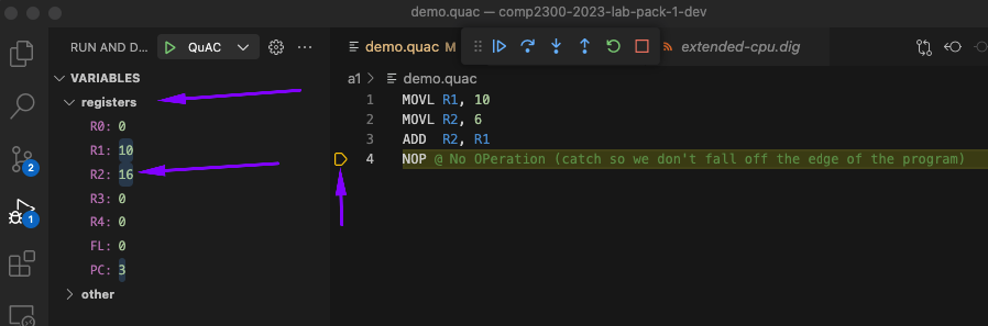
You can see where the debugger is up to from the little yellow indicator on the left, it sits on the next instruction to be executed. In the
program above, that’s a NOP, what is a NOP actually doing behind the scenes?
Our program as it stands is a little boring, let’s get some loading and storing going on.
To do this, we need to learn a little about directives. For now, there is only really one that you need to know about:
.word 0x____ @ Allows you to specify a 16 bit number instead of an instruction in the program
With this, we can do a couple things:
- Specify an instruction using hex instead of an instruction code (including new instructions that we haven’t defined in
quac.jsonwhich you’ll see in the next exercise) - Specify a value we can load, modify and store back to
Copy the following code into your main.quac file (deleting the existing code)
MOVL R1, 10
MOVL R2, 6
ADD  R2, R1
MOVL R3, 4
.word 0xFFFF @ SUB R2, R3
NOP @ (catch so we don't fall off the edge of the program)
NOP @ (catch so we don't fall off the edge of the program)
Here is a converter to help you out:
| Decimal | |
| Hex | |
| Binary |
Modify the 0xFFFF value so that the instruction in line 5 performs the SUB R2, R3 operation. Refer to the
SUB full instruction definition for the machine code.
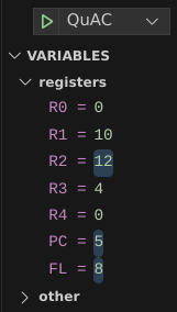
Again, if all went well then your register view should look like this after stepping through your program.
Now let’s get some loading and storing going on. Copy the following program into your main.quac file but make sure to replace line 5 with the correct instruction code that you calculated in the previous do block (deleting the existing code).
MOVL R1, 10
MOVL R2, 6
ADD  R2, R1
MOVL R3, 4
.word 0xFFFF @ SUB R2, R3
NOP @ Load the value at address R2 into R1
NOP @ Add R3 to the value loaded into R1
NOP @ Store the value in R1 at the address in R2
NOP @ Set R1 back to 0
NOP @ Load the value at address R2 into R1
NOP @ If all went well, then by this line R1 should be 46
NOP @ (catch so we don't fall off the edge of the program)
.word 42 @ Important! This MUST be at line 13 (address 12)
Replace the NOP instructions on lines 6 - 10 with what the comment says the line should be doing. Run your program through the debugger and see if R1 = 46 by line 11.
Exercise 6: Adding custom instructions#
For the final exercise, we’re going to add an extra instruction to your CPU. To
do this, you’ll need to modify the quac.json file that is present in the lab-06
directory. If needed, you can re-download a fresh copy
here.
There is already a good section about this on the assembler page, so go read that and come back once you have.
There seems like there is a lot going on there, but once you understand how it works it isn’t too difficult. For this exercise we are going to add a new pseudo-instruction1.
This pseudo-instruction is going to be called RESET, it will take in a register and set that registers value to 0. It will be a pseudo-instruction
for MOVL RD, 0.
To start, we are going to take a copy of MOVL (imm) from quac.json and paste it at the bottom of the instructions object, just below JP.
Here is the MOVL (imm) definition for reference.
"MOVL (imm)": {
    "syntax": "MOVL? <RD:reg>, <IMM8:uint8>",
    "machine": "0000 C RD IMM8",
    "semantic": "RD := 0000 0000 IMM8",
    "description": "Zero extends IMM8 to a 16 bit value and stores it in RD",
    "pseudo": false,
    "class": "imm"
}
After pasting in this copy, the bottom of our quac.json file should look like this:
        },
        "JP": {
            "syntax": "JP? <IMM8:uint8>",
            "machine": "0000 C 101 IMM8",
            "semantic": "PC := 0000 0000 IMM8",
            "description": "Jump to the given immediate value address. (alias for `MOVL PC, IMM8`)",
            "pseudo": true,
            "class": "imm"
        },
        "MOVL (imm)": {
            "syntax": "MOVL? <RD:reg>, <IMM8:uint8>",
            "machine": "0000 C RD IMM8",
            "semantic": "RD := 0000 0000 IMM8",
            "description": "Zero extends IMM8 to a 16 bit value and stores it in RD",
            "pseudo": false,
            "class": "imm"
        }
    }
}
Note the , added after the } for the JP entry. If we are adding new entries to an object then we need to make sure we add a comma (,) to the previous
entry, so it is clear that we are extending the object.
Now that we have that in, let’s break down the changes we are going to make line by line:
Name#
"MOVL (imm)"is the name for our instruction, let’s change that to:"RESET"
Syntax#
"syntax": "MOVL? <RD:reg>, <IMM8:uint8>"is the syntax for our instruction, a better breakdown for this is here, but for our purposes, we want to change the line to:"syntax": "RESET? <RD:reg>", where:RESET- the text for our instruction?- we want our instruction to include a bit that indicates if we want the instruction to run conditionally on the zero flag<RD:reg>- we are specifying the register that we want to reset as part of the instruction
Machine#
"machine": "0000 C RD IMM8"is what the machine code is going to look like for our instruction, we want to change this line to:"machine": "0000 C RD 0000 0000", where:0000- is the OP Code for our instruction (the same asMOVL (imm))Cis our condition flag indicator for zeroRDis the 3 bit code forRD0000 0000is the 8 bit immediate value for 0
Semantic#
"semantic": "RD := 0000 0000 IMM8"is what our instruction actually does, we want to change the line to:"semantic": "RD := 0000 0000 0000 0000", whereRDis the destination register\:=is the assignment operator, in other words the value ofRDis going to be …0000 0000 0000 0000the 16 bit value for0
Description#
"description": "Zero extends IMM8 to a 16 bit value and stores it in RD",is what our instruction actually does in a sentence, we want to change this to:"description": "Sets RD to 0"or something similar
Pseudo#
"pseudo": falsetells us that the instruction is not a pseudo instruction, because the one we are creating is a pseudo instruction, we change this totrue
Class#
"class": "imm"generally tells us what kind of instruction this is, hereimmmeans immediate, which is the same as our new instruction, so we can leave this as is.
This leaves us with the following entry in quac.json:
"RESET": {
    "syntax": "RESET? <RD:reg>",
    "machine": "0000 C RD 0000 0000",
    "semantic": "RD := 0000 0000 0000 0000",
    "description": "Sets RD to 0",
    "pseudo": true,
    "class": "imm"
}
We can test that our change has worked by changing line 9 of our assembly program from the previous exercise to:
RESET R1
Create another custom pseudo-instruction called DOUBLE which doubles a
register value.
Conclusion#
We hope the last three weeks were fulfilling for you and that you learned a lot. If you have made it through all this, you now have a working CPU that satisfies the QuAC ISA for the assignment.
Now is a good time to document your design decisions to implement all the instructions. Note that you will need to recall all these details when writing the report for the assignment.
You have been pushing your work to GitLab, right?
-
An instruction that can be synthesised from existing instruction(s) ↩