Outline#
Before starting this pre-lab it is expected that you will have already picked up your microbit in the week 6 lab. If this isn’t the case then you can continue with the lab using the emulator, but please get in contact with us about collecting a microbit asap.
In this pre-lab you will:
- connect your microbit to the computer
- create your first ARM assembly program using the VSCode IDE
- compile, run and debug your first ARM program
Introduction#
First let me say congratulations on completing the first half course! I hope you’ve been enjoying the content so far. While the first half of the course focused on the architecture of a cpu, the second half focuses on programming and interacting with one.
This lab marks the start of the microbit section of the course, everything you do from here on out will be using the microbit and these labs are your opportunity to learn the core concepts by putting them into practice. They are also your chance to explore and ask questions. If you don’t understand all of what’s going on in this lab, that’s ok—for two reasons:
- this is just the first microbit lab, so we’ll cover all this stuff in detail in both lectures and future labs
- there are no stupid questions in this course, so the lab sessions are the time to speak up
Task 0: Setting Up the COMP2300 Microbit Software Environment#
You should have already setup your computer earlier in the course, however if you haven’t, or you didn’t setup VSCode, then you can refer back to the software setup page. and come back here once you have finished setup.
Task 1: Connecting the Microbit to the Computer#
The microbit connects to the lab computer (or your personal laptop) via a micro-USB cable.
Your microbit isn’t super fragile, but you’ll still need to be careful when carrying it around. Here are a few tips:
- pack the board up in its bag/box when you’re not using it
- make sure the USB cable is unplugged before putting into your bag
Once you’ve received your new microbit, plug it in to the computer—the full-size USB end goes into the computer (you may need to get an adapter or different cable if you only have usb-c ports), and the small end of the USB cable goes into the connector at the top edge of your microbit.
You’ll find at this stage that your microbit starts playing a little default program. Feel free to enjoy the little game/demo that comes on it, you’ll have to erase it in a minute!
Task 2: Your First Microbit Program#
Now that you’ve connected your board to the computer it’s time to turn everything on and see if it works. This exercise is a bit longer, so it’s broken down into stages: clone, edit, build & run.
Fork & Clone#
- fork the microbit template repo to your user account
(i.e.
uXXXXXXX) - clone it to your local machine
You can do the git clone step in the terminal, or your favourite git client,
it doesn’t matter. If you like, you can use VSCode’s built-in git support:
here’s a link to the general docs on this
view,
and here’s the specific instructions on how to clone a
repo.
Once you’ve cloned the repo, you must make sure to open it as a folder. You can do
this by doing File -> Open Folder... -> comp2300-2024-microbit-template. If you don’t open
this folder, the COMP2300 VSCode extension won’t know how to build your code. In the future
when you clone the lab pack repo, you will also need to open each week’s folder before
you begin for the same reason.
Once you’ve done that you should see something like this:
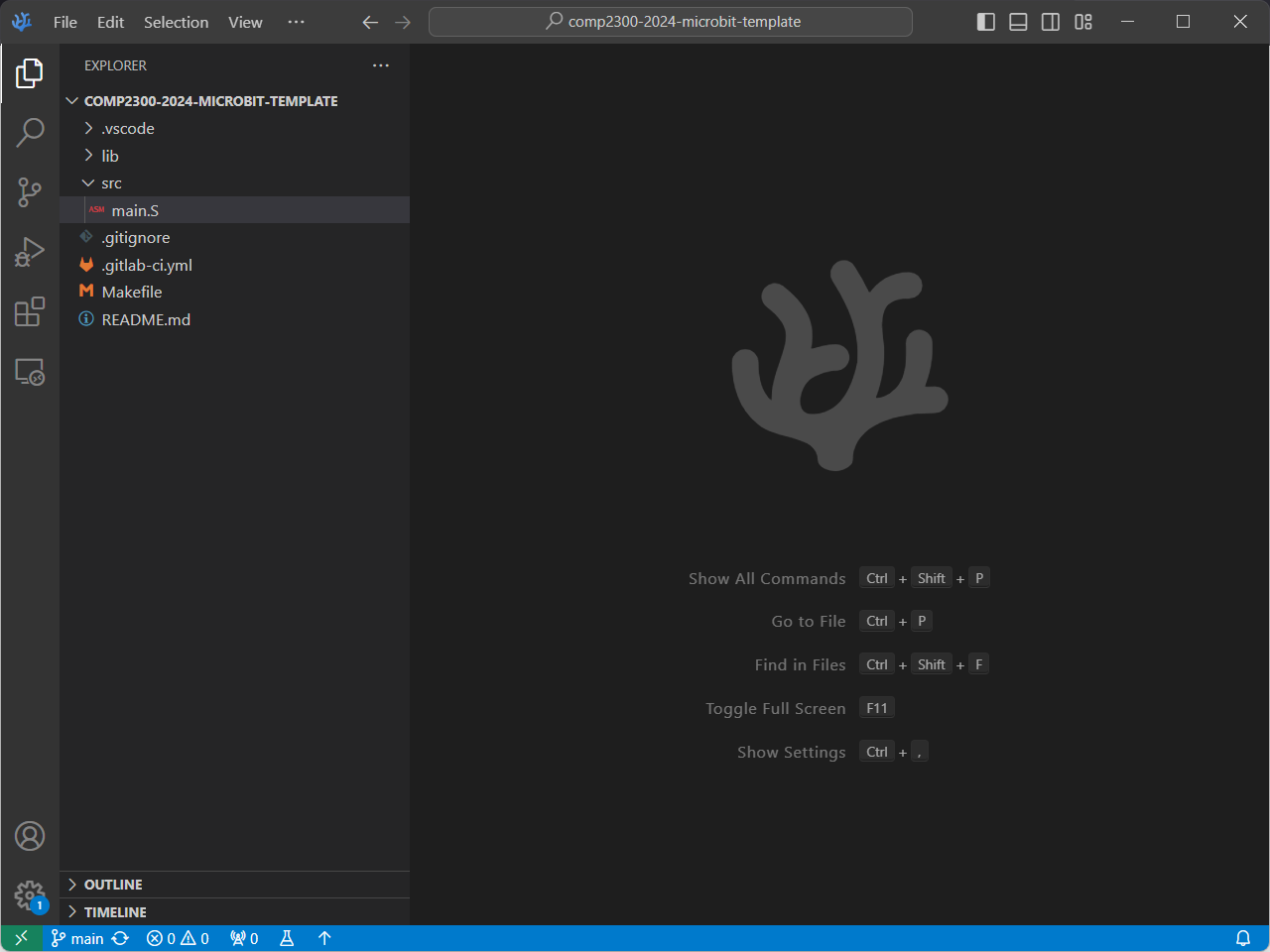
Again, the VSCode docs have a good explanation of the user interface.
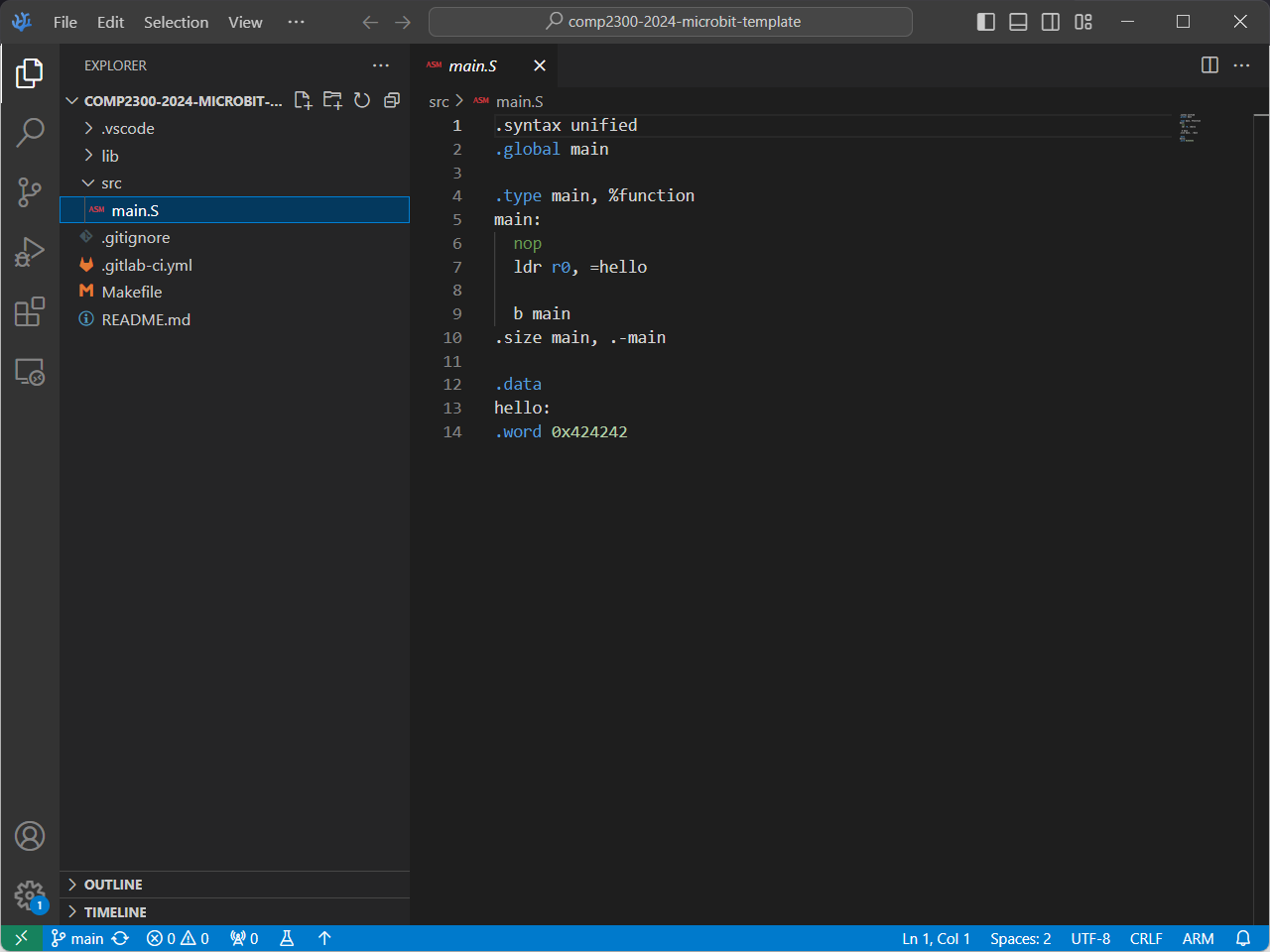
Now, in the Explorer view, open the src/main.S file, you should see
something like this:
Edit#
Add some code so that main.S looks like this:
.syntax unified
.global main
.type main, %function

main:
  mov r1, 0

loop:
  add r1, 1
  b loop
Even if you’re not that familiar with ARM assembly programs, what do you think this does?
Save the file when you’re done. Don’t worry if you don’t understand all the details at this stage—the goal for this part of the lab is just to plug things in, turn them on, and make sure that everything’s working. If you have any problems, get in touch on the forum.
Build#
You can build (or compile—they mean the same thing in this context) your
program using the Build command (COMP2300: Build in the command
palette).
You’ll see some stuff printed to the
terminal (near
the bottom of your VSCodium window), and when it’s done it should look something
like this:
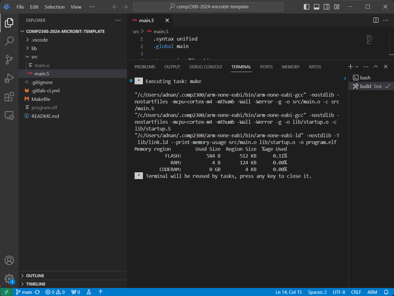
The compilation process takes all the code (text files), translates them into binary instructions for the target Instruction Set Architecture (ISA)— ARMv7 in this case—and links them together into a binary file (image). You can learn more about it here if you want to read ahead, but you’ll also get familiar with it throughout this course.
Upload#
If for some reason you don’t have a microbit and are using the emulator, skip to the next step :) You’ll learn how to get programs onto the emulator there.
You’ve built the program on your computer. To run it on your
microbit you need to upload it with the Upload (COMP2300: Upload)
command. Again, afterward it should look something like this:
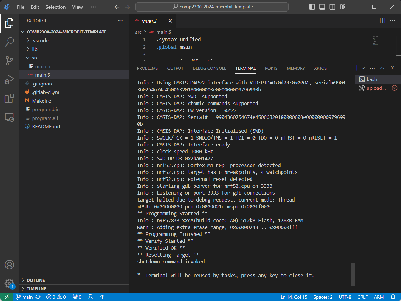
If you get errors at this point, then they’ll be printed (probably in red) in the terminal. Try and figure out what’s going wrong yourself, also checkout the troubleshoot section in software setup
Run & Debug#
When you upload your program to the microbit, it starts running it automatically.
To debug the program (stepping it through, inspecting the CPU & memory states), we’ll use VSCodium’s built-in debugger—an invaluable tool for making things work right when we’re writing programs for the microbit. You may have used a debugger like this before, or you may not have—that’s ok! We’ll lead you through the basics in the labs over the next couple of weeks.
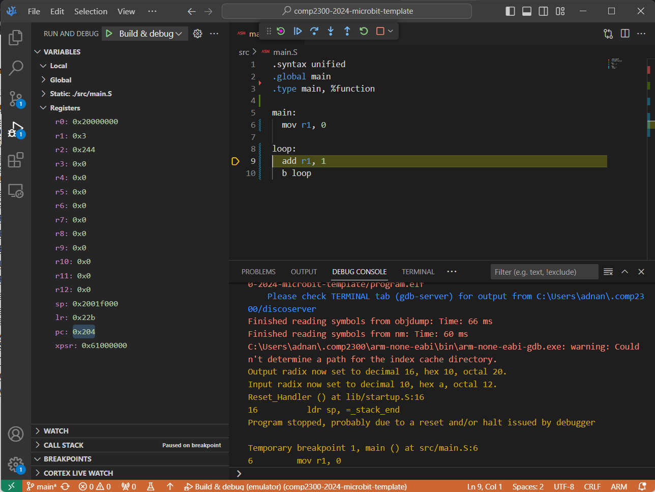
Open up the Debug view and make sure “build & debug” is selected (if you are using the emulator, select “build & debug (emulator)”).
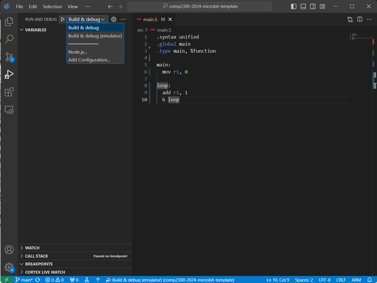
Click the green play button to run your program, pausing (“breaking”) on entry.
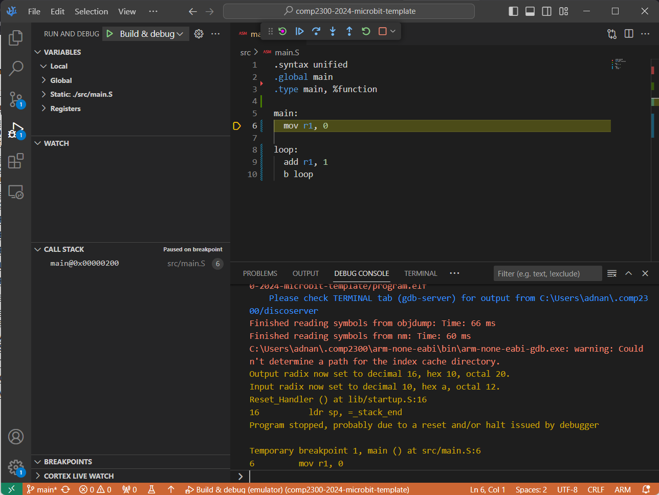
The highlighted yellow line of assembly code (shown in the above screenshot)
represents where the program is “up” to (next instruction to execute).
When you first start it running, the
IDE creates a breakpoint at the
main: label in your program, so when your program reaches that line of code it
stops and waits for further instructions (from you!).
At this point, you can step through the code one instruction at a time using the debug controls:
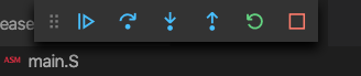
What do all these debug control buttons do? Play around with them —can you see what effect they’re having on the program executing on your microbit? Are you excited?
If you want your program to keep running (i.e. to “unpause” the program) just hit the blue play button (although it’s called continue rather than play when you’re debugging, because it continues after you last paused the execution). Once it’s running, you can pause it again by hitting the pause button, and even stop it with the red stop button.
Once it’s stopped, you can restart the whole process again in a new debugging session by going back to the start of these instructions.
Sometimes the debuggers are a bit flaky, and get into some problems. You’ll get the hang of recognising when things have gone wrong & how to fix them. Remember that it’s ok to use the stop or restart buttons to try and get things back on track, or (worst-comes-to-worst) unplug and re-plug your microbit.
You can also examine the values of your registers in the REGISTERS viewlet under the Debug View (see the bottom left corner in the below screenshot):
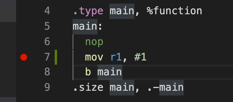
If you want to control exactly where the system pauses for debugging, you can set a new breakpoint by clicking in the left-hand “gutter” (or margin) of the code view in the IDE. You should see a little red dot appear:
The program isn’t running on the computer in front of you (well, unless you’re using the emulator… if you are then ✨imagine✨!)—it’s running on your microbit. What does that mean? What are the implications for the way you run & debug your program?
Now that you have verified that you can edit, build, and debug a
microbit program, create a new folder tasks in the top level repo directory, and copy the code into
a new file tasks/task-2.S. Commit and push your changes with the message “completed task 2”.
Make sure that your task-2.S file is in the seperate tasks folder and not in the src folder,
since otherwise, the assembler will complain about multiple definitions of the main function.
All files in the src folder are assembled, which allows you to split code across several files
(a feature we’ll use later)!
You will notice that the microbit template repo has a CI on it on Gitlab. For the microbit labs, the CI will generally be testing if your code builds (assembles) correctly.
Task 3: Starting with the Basics#
Continuing on with the labs, you will find these references useful (no need to look at them just yet, we’ll step you through when you’ll need each one):
-
Group#
Operation#
Syntax#
Semantic#
Flags#
Arithmetic#
AdditionSubtractionMultiplicationDivisionadd {s}<c><q> {<Rd>,} <Rn>, <Rm> {,<shift>} adc {s}<c><q> {<Rd>,} <Rn>, <Rm> {,<shift>} add {s}<c><q> {<Rd>,} <Rn>, #<const> adc {s}<c><q> {<Rd>,} <Rn>, #<const> qadd <c><q> {<Rd>,} <Rn>, <Rm> sub {s}<c><q> {<Rd>,} <Rn>, <Rm> {,<shift>} sbc {s}<c><q> {<Rd>,} <Rn>, <Rm> {,<shift>} rsb {s}<c><q> {<Rd>,} <Rn>, <Rm> {,<shift>} sub {s}<c><q> {<Rd>,} <Rn>, #<const> sbc {s}<c><q> {<Rd>,} <Rn>, #<const> rsb {s}<c><q> {<Rd>,} <Rn>, #<const> qsub <c><q> {<Rd>,} <Rn>, <Rm> mul <c><q> {<Rd>,} <Rn>, <Rm> mla <c> <Rd>, <Rn>, <Rm>, <Ra> mls <c> <Rd>, <Rn>, <Rm>, <Ra> umull <c> <RdLo>, <RdHi>, <Rn>, <Rm> umlal <c><q> <RdLo>, <RdHi>, <Rn>, <Rm> smull <c> <RdLo>, <RdHi>, <Rn>, <Rm> smlal <c> <RdLo>, <RdHi>, <Rn>, <Rm> udiv <c> <Rd>, <Rn>, <Rm> sdiv <c> <Rd>, <Rn>, <Rm> Rd(n) := Rn + Rm{shifted} Rd(n) := Rn + Rm{shifted} + C Rd(n) := Rn + const Rd(n) := Rn + const + C Rd(n) := saturated (Rn + Rm) Rd(n) := Rn - Rm{shifted} Rd(n) := Rn - Rm{shifted} - not (C) Rd(n) := Rm{shifted} - Rn Rd(n) := Rn - const Rd(n) := Rn - const - not (C) Rd(n) := const - Rn Rd(n) := saturated (Rn - Rm) Rd(n) := (Rn*Rm) Rd := Ra + (Rn*Rm) Rd := Ra - (Rn*Rm) RdHi:RdLo := unsigned_64_bit (Rn*Rm) RdHi:RdLo := unsigned_64_bit (RdHi:RdLo + (Rn*Rm)) RdHi:RdLo := signed_64_bit (Rn*Rm) RdHi:RdLo := signed_64_bit (RdHi:RdLo + (Rn*Rm)) Rd := unsigned_32_bit (Rn/Rm); rounded towards 0 Rd := signed_32_bit (Rn/Rm); rounded towards 0 NZCV NZCV NZCV NZCV Q NZCV NZCV NZCV NZCV NZCV NZCV Q - - - - - - - - - Bit operations#
LogicTestsand {s}<c><q> {<Rd>,} <Rn>, <Rm> {,<shift>} bic {s}<c><q> {<Rd>,} <Rn>, <Rm> {,<shift>} orr {s}<c><q> {<Rd>,} <Rn>, <Rm> {,<shift>} orn {s}<c><q> {<Rd>,} <Rn>, <Rm> {,<shift>} eor {s}<c><q> {<Rd>,} <Rn>, <Rm> {,<shift>} and {s}<c><q> {<Rd>,} <Rn>, #<const> bic {s}<c><q> {<Rd>,} <Rn>, #<const> orr {s}<c><q> {<Rd>,} <Rn>, #<const> orn {s}<c><q> {<Rd>,} <Rn>, #<const> eor {s}<c><q> {<Rd>,} <Rn>, #<const> cmp <c><q> <Rn>, <Rm> {,<shift>} cmn <c><q> <Rn>, <Rm> {,<shift>} tst <c><q> <Rn>, <Rm> {,<shift>} teq <c><q> <Rn>, <Rm> {,<shift>} cmp <c><q> <Rn>, #<const> cmn <c><q> <Rn>, #<const> tst <c><q> <Rn>, #<const> teq <c><q> <Rn>, #<const> Rd(n) := Rn ∧ Rm{shifted} Rd(n) := Rn ∧ ¬Rm{shifted} Rd(n) := Rn ∨ Rm{shifted} Rd(n) := Rn ∨ ¬Rm{shifted} Rd(n) := Rn ⊕ Rm{shifted} Rd(n) := Rn ∧ const Rd(n) := Rn ∧ ¬const Rd(n) := Rn ∨ const Rd(n) := Rn ∨ ¬const Rd(n) := Rn ⊕ const Rn - Rm{shifted} Rn + Rm{shifted} Rn ∧ Rm{shifted} Rn ⊕ Rm{shifted} Rn - const Rn + const Rn ∧ const Rn ⊕ const NZCV NZCV NZCV NZCV NZCV NZCV NZCV NZCV NZCV NZCV NZCV NZCV NZCV NZCV NZCV NZCV NZCV NZCV Register moves#
MoveShift/Rotatemov {s}<c><q> <Rd>, <Rm> mov {s}<c><q> <Rd>, #<const> lsr {s}<c><q> <Rd>, <Rm>, #<n> lsr {s}<c><q> <Rd>, <Rm>, <Rs> asr {s}<c><q> <Rd>, <Rm>, #<n> asr {s}<c><q> <Rd>, <Rm>, <Rs> lsl {s}<c><q> <Rd>, <Rm>, #<n> lsl {s}<c><q> <Rd>, <Rm>, <Rs> ror {s}<c><q> <Rd>, <Rm>, #<n> ror {s}<c><q> <Rd>, <Rm>, <Rs> rrx {s}<c><q> <Rd>, <Rm> Rd := Rm Rd := const Rd := Rm{shifted-right by <n>}; filled with 0’s, C := last shifted-out Rd := Rm{shifted-right by Rs}; filled with 0’s, C := last shifted-out Rd := Rm{shifted-right by <n>}; filled with MSB2, C := last shifted-out Rd := Rm{shifted-right by Rs}; filled with MSB2, C := last shifted-out Rd := Rm{shifted-left by <n>}; filled with 0’s, C := last shifted-out Rd := Rm{shifted-left by Rs}; filled with 0’s, C := last shifted-out Rd := Rm{rotated-right by <n>}; C := MSB2 of result Rd := Rm{rotated-right by Rs}; C := MSB2 of result Rd := Rm{rotated-right by 1 including carry bit} NZ NZC NZC NZC NZC NZC NZC NZC NZC NZC NZC Load & Store#
OffsetPre-OffsetPost-OffsetIndexedLiteralPositive stackNegative stackldr <c><q> <Rd>, [<Rb> {, #+/-<offset>}] str <c><q> <Rs>, [<Rb> {, #+/-<offset>}] ldr <c><q> <Rd>, [<Rb>, #+/-<offset>]! str <c><q> <Rs>, [<Rb>, #+/-<offset>]! ldr <c><q> <Rd>, [<Rb>], #+/-<offset> str <c><q> <Rs>, [<Rb>], #+/-<offset> ldr <c><q> <Rd>, [<Rb>, <Ri> {, lsl #<shift>}] str <c><q> <Rs>, [<Rb>, <Ri> {, lsl #<shift>}] ldr <c><q> <Rd>, <label> ldr <c><q> <Rd>, [PC, #+/-<offset>] stmia <c><q> <Rs>!, <registers> ldmdb <c><q> <Rs>!, <registers> stmdb <c><q> <Rs>!, <registers> ldmia <c><q> <Rs>!, <registers> Rd := [Rb±offset] .[Rb±offset] := Rs Rb := Rb±offset; Rd := [Rb]; Rb := Rb±offset; [Rb] := Rs; Rd := [Rb]; Rb := Rb±offset .[Rb] := Rs; Rb := Rb±offset Rd := [Rb + Ri{shifted-left}] .[Rb + Ri{shifted-left}] := Rs Rd := [label] Rd := [PC±offset] for Ri in registers: [Rs] := Ri; Rs := Rs + 4 for Ri in reverse registers: Rs := Rs - 4; Ri := [Rs] for Ri in reverse registers: Rs := Rs - 4; [Rs] := Ri for Ri in registers: Ri := [Rs]; Rs := Rs + 4 - - - - - - - - - - - - - - Branch#
Branch on flagsTest & branchTable basedb <c><q> <label> bl <c> <label> bx <c> <Rm> blx <c><q> <Rm> cbz <q> <Rn>, <label> cbnz <q> <Rn>, <label> tbb <c><q> [<Rn>, <Rm>] tbh <c><q> [<Rn>, <Rm>, lsl #1] if c then PC := label if c then LR := PC_next; PC := label if c then PC := Rm if c then LR := PC_next; PC := Rm if Rn= 0 then PC := label if Rn! 0 then PC := label branch to [PC + Rm’s byte in the table starting at Rn)]; branch to [PC + Rm’s halfword in the table starting at Rn)]; - - - - - - - - Synchronization#
ldrex <c><q> <Rt>, [<Rn> {,#<offset>}] strex <c><q> <Rd>, <Rt>, [<Rn> {,#<offset>}] Rt := [Rn + offset]; mark (Rn + offset) as exclusive memory if exclusive then [Rn + offset] := Rt; Rd := 0 else Rd := 1 - -
Your job in this exercise is to write an assembly program which calculates
2+2 and leaves the result in register 1 (r1).
Remember you can see the values in your microbit’s registers (assuming there’s a debugging session running and the execution is paused) in the registers pane:
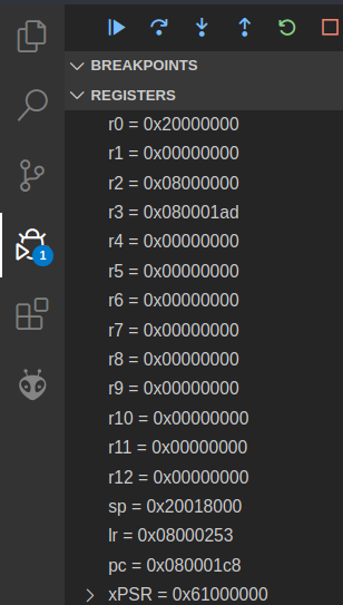
You can set the numeric format for a specific register in the register view. Simply right-click on the register, select “set number format” and then select the desired format. This will help you make sense of the value of a register.
ARM Assembly Syntax#
You should already be familiar with the QuAC ISA syntax from the first half of the course. You should also have seen ARM syntax in the lectures so this should mostly be a summary / refresher.
To assist you with learning the ARM syntax, we’ve prepared a
cheat sheet. It looks pretty intimidating at
first—mostly because it crams a lot of information into a small space.
So let’s pick one line of the cheat sheet—the sub instruction—and pick it apart.
First, the syntax column:
sub{s}<c><q> {<Rd>,} <Rn>, <Rm> {,<shift>}
The first token on the line is the instruction name, and after that is the (comma-separated) argument list.
-
anything in braces (
{}) is optional, e.g. thesat the end ofsub{s}means that it can be eithersuborsubs -
the
<c>and<q>parts relate to the condition codes and opcode size boxes on the second page of the cheat sheet - they’re also optional and you probably won’t need them for this first exercise -
{<Rd>,}is the destination register (e.g.r3orr11), which is optional because if it’s omitted the result will be stored in the<Rn>register (which is why the semantic column saysRd(n) := ...) -
<Rn>, <Rm>are the two operands (arguments) for thesubinstruction -
finally, the optional
{,<shift>}part is related to the barrel shifter (for bit-shifting operations) built alongside the microbit’s ALU - you don’t have to worry about this too much for the moment but it’ll come in handy later
There are a couple of other parts of the syntax which aren’t covered in the
sub instruction:
-
constant values (e.g. numbers) are written normally (e.g.
24for decimal numbers) although you can add a prefix to indicate a different base:0bfor binary (e.g.0b1101101),0ofor octal (e.g.0o125) or0xfor hexadecimal (0xEF20) -
when it comes to load & store operations, square brackets
[]indicate that the instruction should use the memory address in the register, e.g.[r2]tells the microbit to “use the memory address inr2” for that instruction
You won’t need to know all of this stuff to complete this lab, so just remember that it’s here if you need to come back to it. Let’s keep going…
Just like any other programming language, once you understand the syntax you can read and understand the code. While there are more instructions in ARM than QuAC, it is still a small language in comparison to your higher level programming languages (there are only a couple of dozen instructions). What that means for you is that it’s probably easier to read than languages with a richer syntax (I’m looking at you, Haskell).
The semantic column on your cheat sheet describes what the instruction does.
For example, the semantic for the sub instruction is Rd(n) := Rn -
Rm{shifted}, which in English translates to something like:
in the
Rdregister (orRn, if there are only two register operands present) store the result of subtracting the value in theRmregister (with an optional bit-shift, if present) from the value in theRnregister
You can probably see why we use assembly language for telling our CPU what to do rather than English—it’s much less wordy.
The flags column of the cheat sheet specifies which of the special condition
code flags that instruction sets if the optional s suffix is present. (We’ll
cover this in a later lab, but if you’re curious there’s a box on the second
page of the cheat sheet which lists the flags.)
Whew, that was a bit of an information dump. But it was worth picking it apart in detail, since you’ll be looking at the cheat sheet (and ARM instruction syntax) a lot.
The Task#
To actually complete your “2 + 2” task, you’ll need to
- get number
2into a register - add another
2to it and put the result inr1
Write a program that does this into your main.S file.
Look over the cheat sheet—which assembly instructions allow you to specify numeric constants/literals in a register? There are also a number of machine instructions which will implement an addition—which one do you want, and why?
Once you’ve written a program which you think will do what you want, step
through and make sure that the value which r1 holds at the end is actually
4.
Once you have verified that r1 contains 4,
copy the code into a new file tasks/task-3.S. Commit and push your changes with the message “completed task 3”.
FAQ#
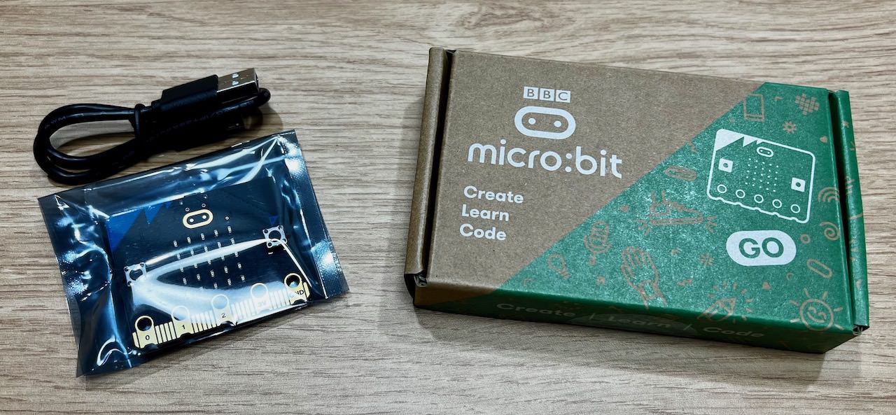
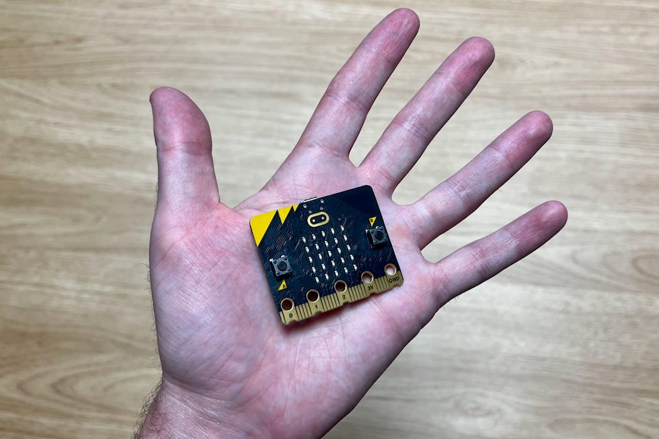
What is a Microbit?#
It’s this little board right here!
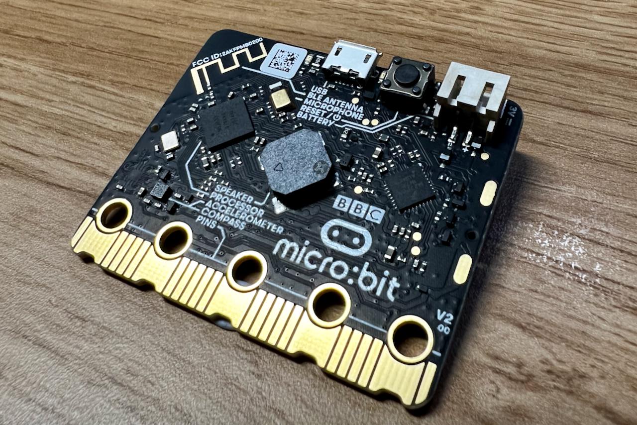
If you want to know more about what is on it, you can have a look at this website.