Under Construction
This page is currently being updated for Semester 1, 2026 and the information present may change or be outdated. Keep checking back regularly to see the most up to date information.
Introduction#
✨ Congratulations on completing the Digital labs ✨!
We hope you have enjoyed the course content so far. While we’ve spent our time in the labs so far building a CPU from the ground up, this week and next we will focus primarily on writing ARM assembly code.
We’ll be using VSCode and an ARM assembler to write and run programs using ARM assembly!
Remember, your Digital assignment is due Wednesday 11:59pm, Week 9! Make sure you write your report and push everything to GitLab!
In the first half of the course, you saw how your CPU is made of logic gates that form different components. You also saw how you can use specially crafted words (i.e. numbers) stored in memory to instruct your CPU to do things (e.g., add two values). You may remember this as forming opcodes (operation codes) and instructions.
Today you will be having a look at the form these opcodes and instructions take in the ARM assembly language, which you’ll be using for the rest of the course.
You’ll also start to see more clearly the connections between what we’ve been
covering in this course and the higher-level programming languages you’re used
to, with “high-level” if statements, for loops, and other structures. This
process of “demystifying” programming is a big part of what this course is
about, so take the time to reflect on what you’re doing and how it fits in with
what you know and do in other programming situations.
Some of the content in this lab might feel like a refresher to what was covered in first half of the course. That’s a good thing! it means you’re actively engaging with and learning the content. Just keep in mind that ARM does differ to QuAC, so make sure you’re still reading everything here carefully.
A good example of this is the fact that we will be using a 32-bit ARM CPU, whereas with QuAC we were
working with a 16-bit CPU. This gives us more room to fit things in the instruction encoding,
so you won’t find things like MOVL anymore, we just have MOV.
There are some resources that will be useful for you throughout these labs:
Task 0: Ensuring your ARM Environment is Set Up#
You should have already setup your computer earlier in the course. If you haven’t (or you didn’t setup VSCode) then you can refer back to the software setup page and return here once you have finished setup.
Fork & Clone#
- fork the ARM assembly lab pack repo to your user account
(i.e.
uXXXXXXX) - clone it to your local machine
You can do the git clone step in the terminal, or your favourite git client,
it doesn’t matter. If you like, you can use VSCode’s built-in git support:
here’s a link to the general docs on this
view,
and here’s the specific instructions on how to clone a
repo.
Once you’ve cloned the repo, you must make sure to open it as a folder. You can do
this by doing File -> Open Folder... -> comp2300-2026-arm-labs. If you don’t open
this folder, the COMP2300 VSCode extension won’t know how to build your code. In the future
when you clone the lab pack repo, you will also need to open each week’s folder before
you begin for the same reason.
Once you’ve done that you should see something like this:
TODO: UPDATE SCREENSHOT!
Again, the VSCode docs have a good explanation of the user interface.
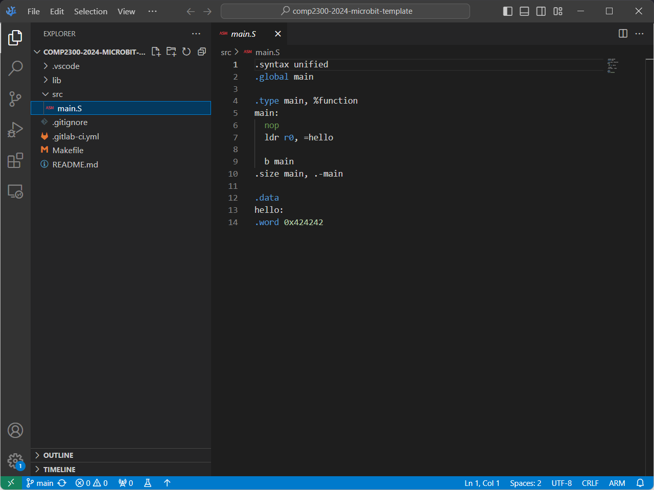
Now, in the Explorer view, open the src/main.S file, you should see
something like this:
TODO: UPDATE SCREENSHOT!
Edit#
Add some code so that main.S looks like the following. Make save the file when you’re done!!
.syntax unified
.global main
.type main, %function

main:
  mov r1, 0

loop:
  add r1, 1
  b loop
Even if you’re not that familiar with ARM assembly programs, what do you think this does?
The mov instruction in ARM assembly is very similar to the movl
instruction from the QuAC ISA, while the b instruction is very similar to
the jp instruction from the QuAC ISA.
Build#
You can build (or compile—they mean the same thing in this context) your
program using the Build command (COMP2300: Build in the command
palette).
You’ll see some stuff printed to the
terminal (near
the bottom of your VSCodium window), and when it’s done it should look something
like this:
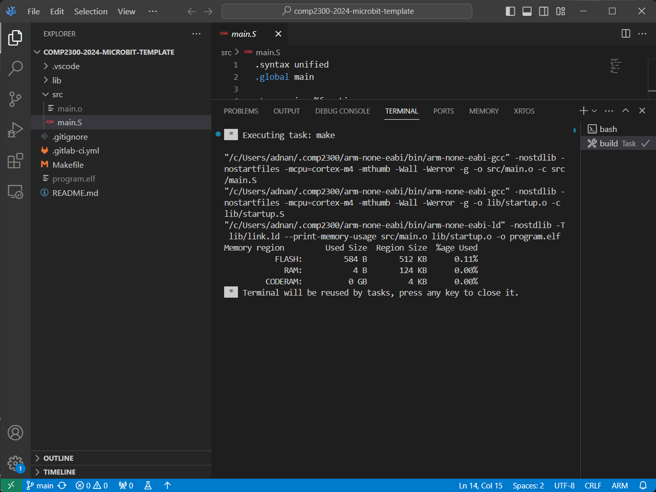
The compilation process takes all the code (text files), translates them into binary instructions for the target Instruction Set Architecture (ISA)— ARMv7 in this case—and links them together into a binary file (image). You can learn more about it here if you want to read ahead, but you’ll also get familiar with it throughout this course.
Run & Debug#
TODO: need to update the explanation here to make it read more smoothly given we don’t have microbits anymore. e.g. explain the emulator, how to use it, how to debug, etc.
To debug the program (stepping it through, inspecting the CPU & memory states), we’ll use VSCodium’s built-in debugger—an invaluable tool for making things work right when we’re writing programs in ARM assembly. You may have used a debugger like this before, or you may not have—that’s ok! We’ll lead you through the basics in the labs over the next couple of weeks.
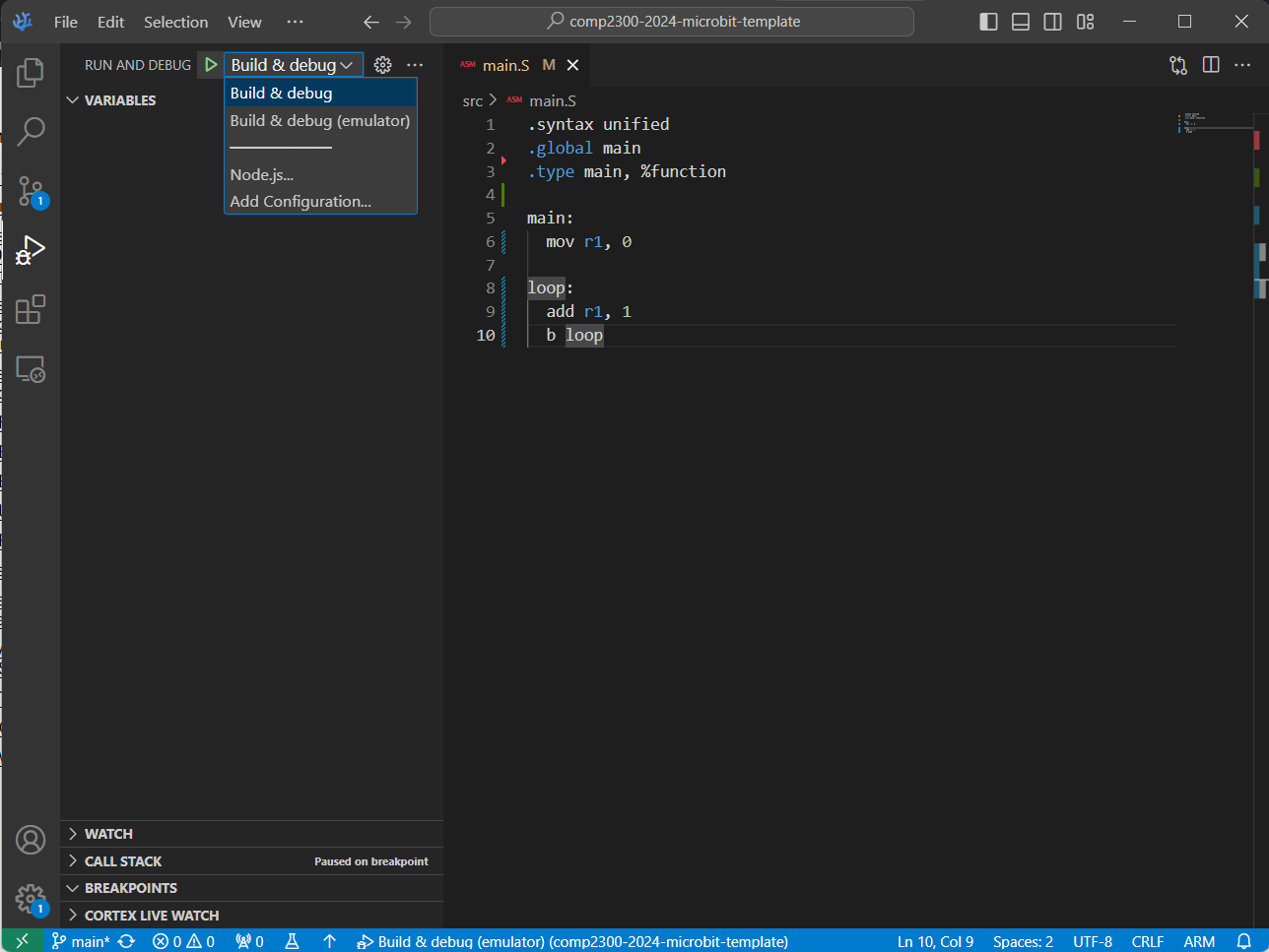
Open up the Debug view and make sure “Build & debug (emulator)” is selected.
Make sure “Build & debug (emulator)” is selected.
TODO: update screenshot!
Click the green play button to run your program, pausing (“breaking”) on entry.
TODO: update screenshot!
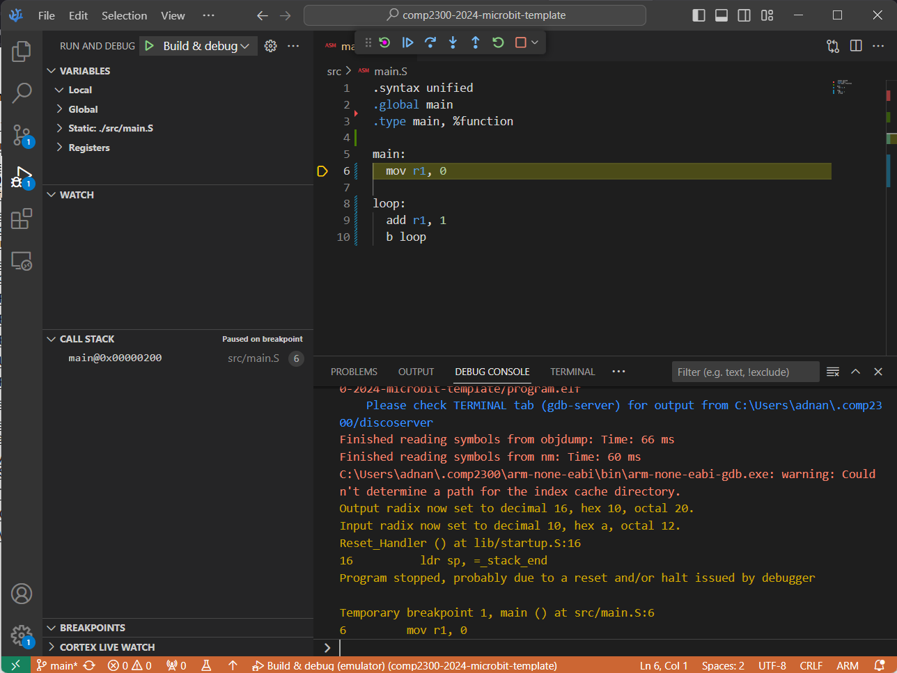
Did you make sure “Build & debug (emulator)” was selected?
The highlighted yellow line of assembly code (shown in the above screenshot)
represents where the program is “up” to (next instruction to execute).
When you first start it running, the
IDE creates a breakpoint at the
main: label in your program, so when your program reaches that line of code it
stops and waits for further instructions (from you!).
At this point, you can step through the code one instruction at a time using the debug controls:
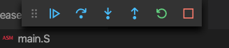
What do all these debug control buttons do? Play around with them —can you see what effect they’re having on the program executing in the emulator? Are you excited?1
If you want your program to keep running (i.e. to “unpause” the program) just hit the blue play button (although it’s called continue rather than play when you’re debugging, because it continues after you last paused the execution). Once it’s running, you can pause it again by hitting the pause button, and even stop it with the red stop button.
Once it’s stopped, you can restart the whole process again in a new debugging session by going back to the start of these instructions.
You can also examine the values of your registers in the REGISTERS viewlet under the Debug View (see the bottom left corner in the below screenshot):
TODO: update screenshot!
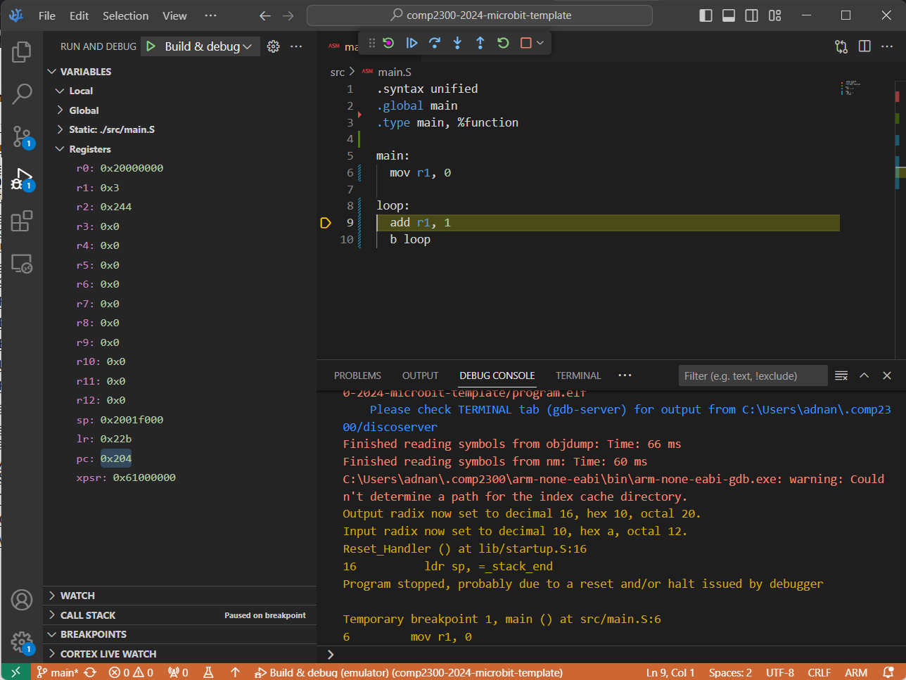
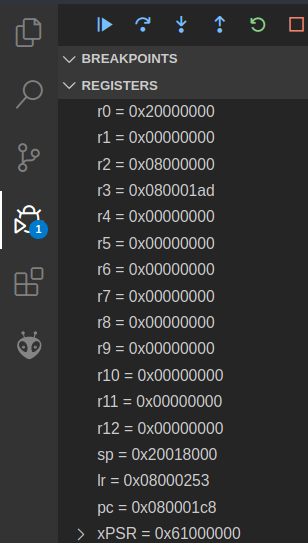
You can set the numeric format for a specific register in the register view. Simply right-click on the register, select “set number format” and then select the desired format. (If this isn’t visible, you may have to click the ‘n’ button at the top right of the register view to disable hex mode). This will help you make sense of the value of a register.
You might notice that unlike your QuAC CPU, the register R0 is not reserved as
an always-zero register.
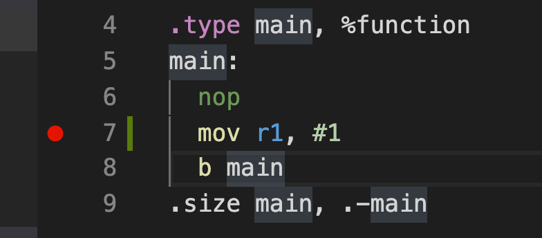
If you want to control exactly where the system pauses for debugging, you can set a new breakpoint by clicking in the left-hand “gutter” (or margin) of the code view in the IDE. You should see a little red dot appear:
Now that you have verified that you can edit, build, and debug an ARM assembly
program, copy the contents of main.S into the file task-0.S in
the tasks folder. Commit and push your changes with the message “completed task 1”.
Make sure that your task-0.S file is in the separate tasks folder and not in the src folder,
since otherwise, the assembler will complain about multiple definitions of the main function.
All files in the src folder are assembled, which allows you to split code across several files
(a feature we’ll use later)!
Overview of ARM Assembly#
Continuing on with the labs, you will find these references useful (no need to look at them just yet, we’ll step you through when you’ll need each one):
- ARM assembly cheat sheet:
- ARM®v7-M Architecture Reference Manual
You should already be familiar with the QuAC ISA syntax from the first half of the course. You should also have seen ARM syntax in the lectures and the mid-semester exam, so this should mostly be a summary / refresher.
To assist you with learning the ARM syntax, we’ve prepared a
cheat sheet. It looks pretty intimidating at
first—mostly because it crams a lot of information into a small space.
So let’s pick one line of the cheat sheet—the sub instruction—and pick it apart.
First, the syntax column:
sub{s}<c><q> {<Rd>,} <Rn>, <Rm> {,<shift>}
The first token on the line is the instruction name, and after that is the (comma-separated) argument list.
-
anything in braces (
{}) is optional, e.g. thesat the end ofsub{s}means that it can be eithersuborsubs -
the
<c>and<q>parts relate to the condition codes and opcode size boxes on the second page of the cheat sheet - they’re also optional and you probably won’t need them for this first exercise -
{<Rd>,}is the destination register (e.g.r3orr11), which is optional because if it’s omitted the result will be stored in the<Rn>register (which is why the semantic column saysRd(n) := ...) -
<Rn>, <Rm>are the two operands (arguments) for thesubinstruction -
finally, the optional
{,<shift>}part is related to the barrel shifter (for bit-shifting operations) built alongside the ARM CPU’s ALU - you don’t have to worry about this too much for the moment but it’ll come in handy later
Think about the similarities and differences with the sub instruction from
your QuAC CPU.
There are a couple of other parts of the syntax which aren’t covered in the
sub instruction:
-
constant values (e.g. numbers) are written normally (e.g.
24for decimal numbers) although you can add a prefix to indicate a different base:0bfor binary (e.g.0b1101101),0ofor octal (e.g.0o125) or0xfor hexadecimal (0xEF20) -
when it comes to load & store operations, square brackets
[]indicate that the instruction should use the memory address in the register, e.g.[r2]tells the CPU to “use the memory address inr2” for that instruction
You won’t need to know all of this stuff to complete this lab, so just remember that it’s here if you need to come back to it. Let’s keep going…
The semantic column on your cheat sheet describes what the instruction does.
For example, the semantic for the sub instruction is Rd(n) := Rn -
Rm{shifted}, which in English translates to something like:
in the
Rdregister (orRn, if there are only two register operands present) store the result of subtracting the value in theRmregister (with an optional bit-shift, if present) from the value in theRnregister
You can probably see why we use assembly language for telling our CPU what to do rather than English—it’s much less wordy.
The flags column of the cheat sheet specifies which of the special condition
code flags that instruction sets if the optional s suffix is present. (We’ll
cover this in a later lab, but if you’re curious there’s a box on the second
page of the cheat sheet which lists the flags.)
Whew, that was a bit of an information dump. But it was worth picking it apart in detail, since you’ll be looking at the cheat sheet (and ARM instruction syntax) a lot.
Throughout this lab you may find the following tool to convert between binary, hexadecimal and decimal representations of 32-bit numbers useful.
| Decimal | |
| Hex | |
| Binary |
Task 1: Loading and Storing#
Throughout the labs you will see “directives” that you can add to your program to store arbitrary data into your program. Some common directives you may see are:
-
.wordwhich you can use to put 32-bit numbers into your program (this comes from the fact that your ARM CPU uses 32-bit “words”). -
.hwordwhich you can use to put 16-bit numbers into your program (similar to.word, but a “half-word”, i.e. 16 bits). -
.asciiwhich you can use to put arbitrary text into your program. This will store the text following the.asciidirective into the program using the ASCII encoding.
This directive uses the ASCII character code to determine exactly what bytes the assembler puts in your program. These bytes are put into memory in the order they are listed — the lowest byte in memory is used to store the first character, the second lowest byte is used to store the second character, and so on.
We can use .ascii to load some new data into register r1 by making your
main.S look like:
.syntax unified
.global main

my:
  .word

.type main, %function
main:
  @ load "COPE" into r1
  ldr r1, cope

  @ fill in the rest of the instructions here!


@ infinite catch loop
inf_loop:
  nop
  b inf_loop
This code introduces a new compiler directive: labels. From the documentation:
A label is written as a symbol immediately followed by a colon
:. The symbol then represents the current value of the active location counter, and is, for example, a suitable instruction operand. You are warned if you use the same symbol to represent two different locations: the first definition overrides any other definitions.
So in the code above there are two new labels: cope and inf_loop. A label
is a way of attaching a human-readable name to a location in your sequence of
instructions (i.e. your program). But always remember that it’s just a location
marker, and once your program is running on your board it will have a specific
memory address which you can store in a register, do arithmetic on, etc.
Using the Memory Viewer#
Once you’ve started running this program in the debugger, you can inspect the value stored at the “cope” label directly.
When the debugger has stopped at main, use VsCode’s Command Palette to run the “COMP2300: View Memory (New Tab)” command:

This will ask you for a memory address (in this case enter 0x200) and a length
(in this case, any number greater than 4 will suffice. The following example
uses a length of “64”). This will open a new
tab in your editor that shows you the values currently stored in memory starting
at address 0x200 and continuing for length bytes:

This is similar to how you would inspect the memory of your QuAC CPU by right-clicking on the RAM component.
What will you see in r1 after the ldr r1, cope line?
Your goal in this exercise is to isolate and shift individual bytes within the
"COPE" word:
- first, change it into
"HOPE"and store inr2 - then, change it into
"HOPS"and store inr3
Note: you do not have to store the word back into memory! In fact, you will not be able to do this because the “HOPS” is written in the code section of memory, which is read-only.
Each of these steps requires isolating and manipulating one 8-bit (1-character) part of the 32-bit word without messing with the rest of it. We will provide you with the following hints to get started:
- The character “C” is encoded as
0x43(67), the character “O” as0x4F(79), the character “P” as0x50(80) and “E” as0x45(69). You should look at the “Printable Character Table” linked above to find out what “H” and “S” are encoded as. - The value you will see in
r1afterldr r1, copeis executed will be0x45504f43. - In the ASCII character encoding you can add 5 to change a
Cinto anH, and add 14 to change anEinto anS. - The new characters need to be shifted back into the correct position and then need to replace the appropriate character in the original word.
- If you have completed this exercise correctly then
r2will equal0x45504f48andr3will equal0x53504f48.
It might be helpful to use a piece of paper here: write out what the "COPE"
data looks like in memory (remember endianness!), and figure out what
shuffles, logical operations, or arithmetic operations you need to make the
transformations into "HOPS". If you’re stuck, think what bit-vector
operations will remove, replace or combine information in your registers (you
have a cheat sheet for this! ARM assembly cheat sheet).
“Shuffles” in this case mean shift operations. In ARM, you have the lsl and lsr
instructions to shift values in registers around by numbers of bits. There are other
types of shifts that you can consult the lectures or the cheat sheet to learn about.
Each individual ascii character takes up one byte, which is equal to 8 bits. What does this tell you about how many bits you need to shift by in order to “target” the different ascii characters?
Here’s a simple exercise to check your understanding:
Suppose you had a number 0xAABBCCDD stored in r2 and the number 1 stored
in register r3. Determine how many bits (and in which direction) would r3
need to be shifted by to:
- Add
1to0xDD(the least significant/0th byte) - Add
1to0xCC(the second least significant/1st byte) - Add
1to0xBB(the second most significant/2nd byte) - Add
1to0xAA(the most significant/3rd byte) - Add
64to0xCC(the second least significant/1st byte)
Click here to see the answers and check your understanding
- To add
1to0xDD, you wouldn’t need to shift the value at all. -
To add
1to0xCC, you will first need to shiftr3left by 8 bits:lsl r3, 8 @ becomes 0x100 add r2, r3 -
To add
1to0xBB, you will first need to shiftr3left by 16 bits:lsl r3, 16 @ becomes 0x10000 add r2, r3 -
To add
1to0xAA, you will first need to shiftr3left by 24 bits:lsl r3, 24 @ becomes 0x1000000 add r2, r3 -
To add
64to0xCCyou will need to shiftr3left by 14 bits. This is because1 << 6is equal to 64, and to target the 1st byte we also need to shift left by8:lsl r3, 14 @ becomes 0x4000 add r2, r3
There are several ways to do this, how many can you think of? Show your program to your neighbour or tutor to get ideas about how it could be done differently.
Finalise your program so that the main function performs the "COPE" ->
"HOPE" -> "HOPS" transformation and leaves the "HOPS" value in r3.
Copy the code into tasks/task-1.S. Commit and push your changes with the
message “completed task 1”. The CI will run a test of your code to verify you
have completed this task correctly.
Task 2: Using Memory#
In the previous we introduced the ascii directive to store the word "COPE"
in your program memory (the section of memory where the ARM CPU looks for
instructions to execute). While it is okay to store data there, we have a
dedicated section of memory for storing data to (the RAM). To access that
section of memory, we need to look at memory sections.
Sections in Memory#
Sections in your program are directives (so they start with a .) to the
assembler that the different parts of our program should go in different
parts of the ARM CPU’s memory space. Some parts of this address space are
for instructions which the CPU will execute, but other parts contain
data that your program can use.
Your program can have as many sections as you like (with whatever names you like) but there are a couple of sections which the IDE & toolchain will do useful things with by default:
-
if you use a
.textsection in your program, then anything after that (until the next section) will be put inFlashas program code for the ARM CPU to execute (referred to a ‘text memory’ from this point) -
if you use a
.datasection, then anything after that (until the next section) will be put inRAMas memory that your program can use to read/write the data it needs to do useful things (referred to as ‘data memory’ from this point)
If you’re interested in what other directives exist, you can check them out here.
When you create a new main.S file, any instructions you put are put in the
.text section until the assembler sees a new section directive.
Here’s an example:
main:
  ldr r0, =main
  ldr r1, =storage

.data
storage:
  .word 2, 3, 0, 0
  .asciz "Computer Architecture"
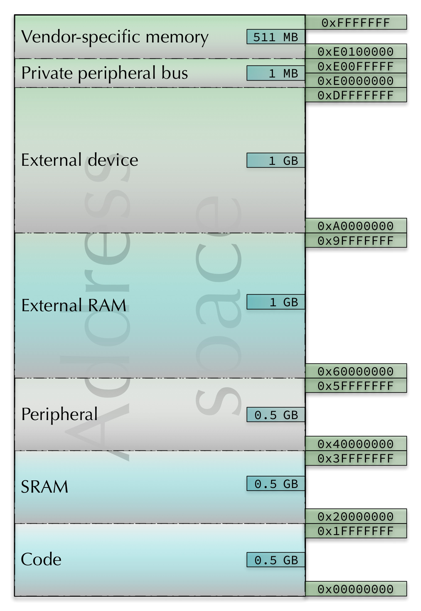
Looking at the CPU’s address space map and running the program above,
where do you think the main and storage parts of your program are ending up?
Can you find the string “Computer Architecture” in memory?
Try and find it in the memory view.
You can interleave the sections in your program if it makes sense:
.text
program:
  @ ...

.data
storage:
  @ ...

.text
more_program:
  @ ...

.data
more_storage:
  @ ...
When you hit build (or debug, which triggers a build) the toolchain will figure out how to put all the various bits in the right places, and you can use the labels as values in your program to make sure you’re reading and writing to the right locations.
If you’re interested in seeing how it’s done, you can look at your project’s linker script, located in your project folder at
lib/link.ld
The Task#
For this task, we’re going to move "COPE" from text memory to data memory.
Copy the following code block into your main.S file.
.syntax unified
.global main

.type main, %function
main:
  @ load the address for "COPE" into r0

  @ load "C" into r1

  @ load "O" into r2

  @ load "P" into r3

  @ load "E" into r4

  @ modify your bit shifting solution to combine the individual characters and turn "COPE" -> "HOPS"

  @ store "HOPS" back into memory at 'hops'


@ infinite catch loop
inf_loop:
  nop
  b inf_loop

.data
@ load COPE from here, don't forget that each ASCII character here is taking up 32 bits (4 bytes) of memory because we are storing them using .word
cope:
  .word 0x43 @ "C"
  .word 0x4f @ "O"
  .word 0x50 @ "P"
  .word 0x45 @ "E"

@ store HOPS here once you have finished
hops:
  .word 0
Comparing the code above with the code from task 2, you’ll notice that we
have added the .data directive and moved cope there. By doing so, we
are now storing "COPE" in data memory instead of text memory.
This also has implications on how we are loading the value from memory, previously we were able to load from text memory using the label directly without loading the address first. This time we aren’t able to do that, instead we have to first get the address of the cope label first. We can do this by using the following syntax:
ldr r0, =cope @ load the address of 'cope' into `r0`.
Once we have the address of the label, we can use
immediate loads
to get the individual bytes of "COPE" into the registers. Then we can use the bit vector
techniques we learned in task 1 to alter the characters and combine them into a single
register.
To verify that your implementation is correct, you need to look at what’s stored at the
hops address in the memory viewer. To do this, you need to get the address of hops;
you can do this by hovering over the hops label while running the program, or by
loading the address of hops into a register and reading the register.
Why do you think we didn’t have to first get a memory address when loading the cope
data in task 1? If you’re curious, you can have a look at
this section of the cheat sheet
We have split apart the individual bytes for "COPE" and are storing them using
the .word directive. This means that each character is taking up 32 bits (4 bytes)
of space. What implications does this have for you? Hint: have a look at the cope
address in the memory viewer if you get stuck.
Complete your program such that the main function loads “COPE” from memory,
performs the same "COPE" -> "HOPE" -> "HOPS" transformation and stores the
result back into memory at the address labelled hops. The result should be
stored as a single 32-bit value.
Verify that your code works by using the memory viewer, then copy the code into
tasks/task-2.S.
Commit and push your changes with the message “completed task 4”.
Task 3: Records#
For the following 3 exercises we will be creating a basic inventory system for the Thunder Muffin paper company. The company only stocks 1 item at the moment, but has plans to increase that.
As such it has asked that you create an inventory system with the following information:
- Product Identification Number (10 digits, starting with a 1)
- Stock level (a value between 0 and 100)
- Restock level (a value between 0 and 100)
- Customer order count (a value between 0 and 9999)
This information will be organised into a record data structure. Data structures are, as the name suggests, used to structure data in a way that is useful for the program, but assembly has the additional challenge that we are working directly with memory. For each piece of data we want to access, we need to be able to compute its memory address.
For records, we have a base address, as well as a static offset associated to each element. Then, to access an element, we just add its associated offset to the base to get its memory address, then load from that address. In this task, we will use a record that looks like this:
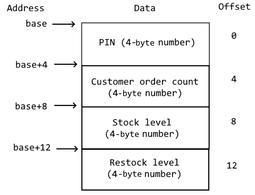
Records can contain elements of different size. E.g. you can store a 1-byte character at offset 0, a 4-byte integer at offset 1 and a 24-byte string at offset 5. But the elements must be of fixed size, i.e. cannot grow during the program’s execution. Look at the assembly data structures lecture for more info.
TODO: show them how to do base+offset addressing ARM lol
The Task#
The company wants you to initialize their first product in the inventory system, they have provided you with the following information:
- Product Identification Number (PIN):
1234567890 - Customer order count:
2008 - Stock level:
53 - Restock level:
50
Copy the following code into your main.S file:
.syntax unified
.global main

.type main, %function
main:
  @ code to initialize plain_a4 goes here


@ infinite catch loop
inf_loop:
  nop
  b inf_loop


.data
plain_a4:
  .word 0, 0, 0, 0
This line:
.word 0, 0, 0, 0
Is equivalent to the following, which you saw in the last task:
.word 0
.word 0
.word 0
.word 0
The difference being it is much more compact. It is okay to use either in your code, and you should use whichever style, or combination of them, that makes sense.
The plain_a4 record has been initialized with 4 0 values. The record is expected to appear
in the order of:
- Product Identification Number (PIN)
- Customer order count
- Stock level
- Restock level
The load and store section of the
cheatsheet will be useful to you. It is also worth noting that you can use
ldr r0, =SOME_NUMBER_HERE to put a number of any size into a register
- eg:
ldr r1, =5403035
As in Task 4, you can verify your implementation works correctly by looking at the
data at the memory location pointed to by plain_a4 in the memory viewer. Follow
the same method as there to find the value of the label’s address.
Remember that the syntax for ldr is ldr rd, [ra] not ldr rd, ra! If you forget
the square brackets around the second register, it’ll give you a very perplexing error
message (something about a T32_OFFSET_IMM)!
Complete your program such that the main function initializes the plain_a4 record
with the information provided above. Verify that your code works
by using the memory viewer, then copy the code into tasks/task-3.S.
Commit and push your changes with the message “completed task 3”.
Task 4: Customer Orders#
Now that you have the record initialized correctly, its time to start adding some functionality to the inventory system. Here is the first action to implement
- customer order:
- Customer order count := Customer order count + 1
- Stock level := Stock level - 1
Write a series of assembly instructions to perform this action after you have initialized plain_a4.
At this point, the inventory system only has one action, so the only way for
the code to proceed is to keep performing that action. We can do that with a
branch instruction: b.
This instruction tells the ARM CPU to “branch” (sometimes called a jump on other
CPU types2) to a different part of the code. You can specify the “destination” of
the branch in a bunch of different ways, including using a label, or a constant
value (if you know exactly what address you want to go to ahead of time) or even
the address in a register. If you’ve wondered how to get your program to do
something other than just keep following the instructions from top to bottom,
branching is the answer.
Add a label and a branch instruction to modify your program so that the inventory system keeps processing customer orders (one after the other) indefinitely.
Hit the continue (play) button in the debug toolbar and let the program run for a while, pausing every now and again to check the inventory system values—what do you notice?
If you’re feeling stuck, we can provide the following hint for how you can:
- Complete the “Customer order count := Customer order count + 1” step
- Repeat the entire operation by branching back to a label
Click here for a hint about how you can approach this task.
@ this goes below your initialisation code
customer_order_loop:
  @ increment customer order count
  ldr r0, =plain_a4
  ldr r1, [r0, 4]
  add r1, 1
  str r1, [r0, 4]

  @ decrement stock level
  @ ... you'll have to write this part yourself! ...

  @ branch back to the "customer_order_loop" label
  b customer_order_loop
Complete your program such that the main function initializes the plain_a4 record
and then performs customer orders indefinitely. Verify that your code works
by using the memory viewer, then copy the code into tasks/task-4.S.
Commit and push your changes with the message “completed task 4”.
Task 5: Status Flags and Condition Codes#
One thing you may have noticed in the previous task is that the stock level continually decreases below zero.
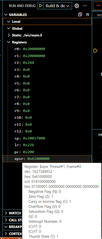
How can you deal with this problem? The answer lies is in the program status
register in every ARMv7 CPU. You can see it in the
Variables viewlet in VSCode under xPSR. Hover over the “xPSR” text to expand the
program status register, as shown below.
Remember we covered the status flags in the first half of the course. Some of these flag values should look familiar to you, as they were a part of the QuAC ISA.
When the CPU executes any instruction with an s suffix (e.g. adds) it
updates these status flags according to the result of the operation. That’s all
the s does—add and adds will leave the exact same result in the
destination register, but adds will update the flags to leave some
“breadcrumbs” about the result (which can be helpful, as you’ll soon see).
In addition to this, if you look at the Tests section of the cheat
sheet then
you can see that there are some instructions specifically used to update the
flags without changing the values in the general purpose registers
(r0 - r12). For example, cmp r0, 10 is the same as subs r0, 10 except
that the value in r0 is left untouched.
Sometimes the status flags are called status bits, or condition flags, or condition codes, or some other combination of those words. They all refer to the same thing—the bits in the program status register.
Write a series of simple programs (e.g. mov some values into registers, then
do an arithmetic operation on those registers) to set
- (a) the negative flag bit
- (b) the zero flag bit
- (c) the carry flag bit and
- (d) the overflow flag bit.
Copy the following into your main.S file, but make sure you saved your previous task first
as we will be coming back to that after this.
.syntax unified
.global main

.type main, %function
main:
  @ set the negative flag

  @ ... your instruction(s) go here ...

  @ set the zero flag

  @ ... your instruction(s) go here ...

  @ set the carry flag

  @ ... your instruction(s) go here ...

  @ set the overflow flag

  @ ... your instruction(s) go here ...

@ infinite catch loop
inf_loop:
  nop
  b inf_loop
If you’re getting bored of stepping through every instruction, don’t forget you
can set breakpoints, these control exactly where your debugger will pause after
clicking ‘continue’ (the green button). You can do this by clicking in the
left-hand “gutter” (or margin) of the code view. You should see a little red
dot appear:
Once your program is working and setting the correct flags, copy the code into
tasks/task-5.S. Commit and push your changes with the message “completed task 5”.
If you're feeling stuck, click here for a sample solution.
mov r0, 0
mov r1, 1
mov r2, 0x7fffffff
subs r3, r0, r1   @ set the negative flag
adds r0, r0       @ set the zero flag
adds r4, r3, 2    @ set the carry flag
adds r5, r2, r2   @ set the overflow flag
Note that the last instruction sets both the negative and overflow flags. As an extension: Can you think of a way to set just the overflow flag?
It might seem like this carry/overflow stuff isn’t worth worrying about because it’ll never happen in real life. But that’s not true. It can cause serious problems, like literally causing rockets to explode. So understanding and checking the status flags really matters :)
Task 6: Restocking Items#
Now that you have a grasp on the condition codes, its time to add another action to our inventory system.
- restock product:
- Stock level := 100
The catch here is that we don’t always want to restock an item. We only want to restock it
if the stock level is <= to the restock level.
Bring your code from Task 4 back into main.S and modify it to perform the following:
- Initialize plain_a4
- Check the stock level
- Restock if stock level is
<=to the restock level - Process a customer order (like you did in Task 4)
- Repeat step 2
To achieve this, you will have to combine your knowledge of condition codes and branching. In short you are going to need to set up a conditional branch that performs a restock when needed.
A general if/else statement using conditional branches looks like this:
  @ ... some code
  cmp r0, r1
  beq if_cond
  b else_cond
if_cond:
  @ code here is executed if cmp r0, r1 set the Z flag
  b end_if
else_cond:
  @ code here is executed if cmp r0, r1 did NOT set the Z flag
end_if:
  @ resume execution after if / else section
If there is only an if and no else then it would look like:
  @ ... some code
  cmp r0, r1
  beq if_cond
  b end_if
if_cond:
  @ code here is executed if cmp r0, r1 set the Z flag
end_if:
  @ resume execution after if / else section
The labels in the above examples are chosen for demonstration purposes, you can label them with whatever you believe makes sense. Remember, labels need to be unique!
Also, you now also have the tools to easily design a “while” loop, which repeats the loop until a certain condition stops holding, using branches and conditional branches. See the assembly control flow lectures for more details.
Complete your program to the above spec. Verify that your code works by stepping through it
and using the memory viewer, then copy the code into tasks/task-6.S.
The example if/else above used the suffix eq to indicate that we should branch
if two registers are equal. Which
condition suffix will
let you branch when the value of a register is Less than or Equal to
another?
Commit and push your changes with the message “completed task 6”.
Task 7: Loops And Arrays#
In the previous tasks, you loaded values from memory, modified them and then stored them back. For this exercise, we are going to be doing this across a series of elements (an array) using a loop.
An array is another common data structure. Unlike a record, which can hold items of different sizes
and types, an array holds values of the same type/size. However, in exchange, an array can be a variable
length of items (whereas records are a fixed size). Arrays in assembly have a base address, and you access
elements at a particular index (e.g. the ith element) by accessing the memory location base + i * size_of_elements.
See the data structures lecture for more info.
In your standard, high level programming languages. If you were asked to add 1 an array of elements, you may end up with something like this:
int[] elements = {1, 2, 5, 6, 3};

for (int i = 0; i < elements.length; i++) {
  elements[i] = elements[i] + 1;
}
In assembly we can do something similar, here is some starter code, copy it into your main.S file:
.syntax unified
.global main

.type main, %function
main:
  @ initialize your loop variables

@ start your loop
add_1_loop:
  @ check if you no longer meet your loop condition, exit if you don't, continue if you do

  @ load your element, add 1, store it back

  @ increase your loop variables

  @ begin the loop again

@ finish the loop
end_add_1_loop:
  nop

@ infinite catch loop
inf_loop:
  nop
  b inf_loop


.data
elements:
.word 1, 2, 5, 6, 3
elements_end:
.word 0 @ This is just here as a place holder, if you had more values in memory then it
        @ wouldn't be necessary
Loop variables#
To perform a loop in assembly, we need a loop condition. For this example we’re going to be
doing a basic for loop over the values in an array, so we will need the following:
- A way to keep track of how many iterations we’ve done
- A way to know how many iterations we need to do
For 1., we can initialize a register, say r2, to 0 and then add to it every loop iteration.
But 2. is where things get a bit more tricky.
Length of an array#
In assembly, we don’t have access to things like .length or len() to determine
what the length of an array of elements is, it is up to us to determine this.
We can do this in a few different ways:
- Zero termination
- The array ends with a 0 value, so when iterating over the array, we check if the value is 0, if it isn’t then we continue. If it is 0, then we know we have reached the end of the array. This has the limitation of not allowing a 0 value in the array contents.
- Known value termination
- Similar to zero termination, this uses some known specific value to determine the end of the array. So like with zero termination, we’re checking for a specific value that will let us know that the array has ended, but again this means that the value can’t be a valid value of the array. This works well when we have a limited range of accepted values in the array.
- Explicit length value
- The length of the array is explicitly defined ahead of time. This could be at a different label, or the first element of the array. If doing this then be careful to be consistent with where the length is stored, and when adding elements to the array the length also needs to be updated.
- Memory length calculation
- If you know the starting address of an array and the ending address of an array, then you can calculate how many memory addresses, and therefore the length, of the array.
For this task, we’re going to use “memory length calculation” to determine the length of the array. In assembly we can do this by:
- Loading the address of the start of the array
- Loading the address of the end of the array
- subtracting the start address from the end address
- optional: divide the result by the size of an element in the array (in bytes)
When we’re dealing with memory address calculations our results will be in # of addresses, where every memory address holds a byte (8 bits) of information. If your elements are longer than this, here they are 4 bytes (32 bits), then the result from subtracting the start address from the end address will not be the amount of elements, but instead the number of memory addresses the elements use.
In this example, we will get a result of 20 for the length of the array (5 elements, 4 bytes each, 5*4 = 20). So if we want to get the number of elements, then we’d need to divide our result (20) by 4 (the amount of bytes each element uses).
Why may we not want to divide the result to get the amount of elements?
Generally, the following instruction(s) will be of interest to you:
Complete your program such that the add_1_loop function uses a loop to increment
all of the values in the elements array by 1. Verify that your code works
by using the memory viewer, then copy the code into tasks/task-7.S.
Commit and push your changes with the message “completed task 7”.
Task 8: Using Labels#
Labels and Loading Arbitrary Numbers into Registers#
Labels are the symbols in your source code followed by a colon
(:), e.g. main:. You’ve probably already got an intuitive feel for how they
work: you put them in your code wherever you like, and when you want to branch
to that part of the program you put the label in as the “destination” part of
the branch instruction. Here’s an example:
loop:
  nop
  @ do stuff

  b loop @ branch back to the "loop" label
In the week 7 lab you even used conditional branches to only branch under certain conditions (i.e., if certain flags were set).
But what are labels, really? Add this code to your main.S file:
.syntax unified
.global main

.type main, %function
main:
  nop
  ldr r0, =an_array


end_check: @ <-- don't remove this label
  nop
inf_loop:
  nop
  b inf_loop

.data
an_array:
.word 0x59d2d9d8, 0x3e682394, 0x5a832dcb, 0x821c34ae
another_array:
.word 0x00000000, 0x00000001
After you step through this line, what’s in r0? You might be wondering what
the = sign is doing in your program. Remember that
instructions are stored in memory with various encodings (some are 16-bit, some
are 32-bit) and that when you use an immediate value constant (e.g. 42) in
an instruction which supports it then the bit pattern for 42
(which is 0b101010) is stored inside that instruction.
This means that if you need to include a constant which is 32 bits long (e.g.
0xABCD1234) then you can’t fit it in the instruction. You may have run into
this problem already—the error message will be something like
Error: invalid constant (ffffffffabcd1234) after fixup
and what it means is that the constant value you’re using is too big (too many bits) for the instruction you’re trying to fit it inside.
Because this is a bit of a pain, the assembler provides a special syntax for
storing larger values in registers. It’s based around the ldr (load register)
instruction, and if you prefix the constant with an = sign then the assembler
will generate the code to load the full value into the register.
So how does this relate to the ldr r0, =an_array instruction above? Well, the
answer is that the labels in your program are just values—they’re the
addresses (in your board’s memory space) of the instruction which occurs after
them in the program. After the linker figures out exactly which address each
label points to, it “replaces” them in the program, so that
ldr r0, =an_array
becomes something like (this is not the address that an_array will actually
have)
ldr r0, =0x80001c8
or whatever address the an_array label ends up pointing to (which may change
every time your program changes).
And since 0x80001c4 (or whatever it is) is just a bit pattern in a register,
you can do the usual arithmetic/logic stuff you can do with any values in
registers:
Write a small program which calculates the size (in memory) of an_array. For
this exercise we will define the size of an_array as the total number of bytes
taken up by all individual elements of the array. The resulting size should be
stored in register r1.
While this is easy enough to work out in your head, you should try and load the address of different labels to determine the total size.
Copy your code into tasks/task-8.S, then commit and push your work to GitLab.
The CI will run a test to check you have completed this tasks successfully.
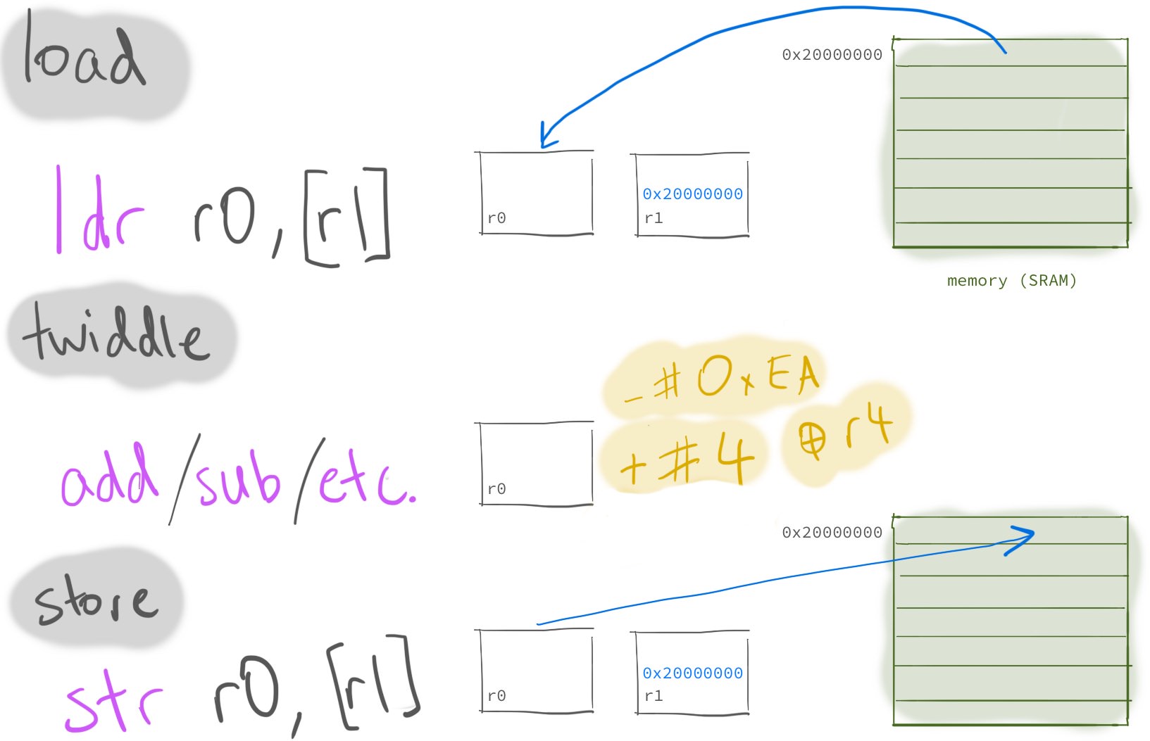
Task 9: The Load-Twiddle-Store Pattern#
The load-twiddle-store pattern is a useful pattern for writing specific bits to certain memory addresses. This is particularly useful for doing things such as controlling hardware via memory mapped I/O. 1
The basic idea is this:
- load some data from memory into a register
- operate on (“twiddle”) the value in the register (e.g. with an
addorandinstruction) - store this new value from the register back into memory
Let’s now make use of a data section to store some (spoilers) data, and attempt to load-twiddle-store.
.syntax unified
.global main

.type main, %function
main:
  ldr r1, =storage
  @ your code starts here

end_check: @ <-- don't remove this label
  nop
inf_loop:
  nop
  b inf_loop

.data
storage:
  .word 2, 3, 5, 0 @ don't change this line
Starting with the code above, use the load-twiddle-store pattern to change
the first four data words to 2 1 7 1 instead of 2 3 5 0. Hint:
first load the storage label using the = instruction, then remember that you
can load and store with an offset from this base address
(check the cheat sheet).
You’ll probably also want to use the memory browser view (like you did in week 7) to watch the values
change in memory.
Note that while you can simply store immediate values and skip the “load” part of the “load-twiddle-store” pattern here, you should still do it anyway.
Copy the code from your load-twiddle-store program into tasks/task-9.S.
Commit and push your changes with the message “completed task 9”. The CI will
run a test to verify you have completed this task successfully.
At this point you’ve completed the main part of this weeks lab — good job!