Under Construction
This page is currently being updated for Semester 1, 2026 and the information present may change or be outdated. Keep checking back regularly to see the most up to date information.
Outline#
Before you attend this week’s lab, make sure:
-
you can read and write basic assembly code: programs with registers, instructions, labels and branching
-
you’re familiar with the basics of functions in the lectures
In this week’s lab you will:
-
write functions (subroutines) to break your program into reusable components
-
pass data in (parameters) and out (return values) of these functions
-
keep the different parts of your code from interfering with each other (especially the registers) using the stack
We will be using the lab-09 folder of a new lab pack repository. Make sure you
fork and clone the new lab pack.
Introduction#
In this week’s lab you will learn how to use functions to simplify accessing the lights on your microbit and how to work with data structures.
Interlude: Functions#
Functions are (usually reusable) blocks of code that have been designed to perform a specific task. Using functions allows us to break a big task (e.g. calculating the mark of a set of students) into smaller ones, which in turn can often be broken down into even smaller ones (e.g. setting and clearing a bit, potentially). How fine-grained you should break things down is a design choice that you get to make when you design your program.
The general pattern for functions look like this:
main:
  @ put arguments in registers
  @ mov r0, ...
  bl foo  @ call function foo
  @ continue here after function returns
  @ ...

.type foo, %function  @ optional, telling compiler foo is a function
@ args:
@   r0: ...
@ result: ...
foo:
  @ does something
  bx lr   @ return to "caller"
.size foo, .-foo      @ optional, telling compiler the size of foo
You will notice that this looks very much like the label stuff we did in the basic machine code lab—and you’d be right. Since functions are just blocks of instructions, labels are used to mark the start of functions.
The only difference between a function and the “branch to label” code you’ve
written already in this course (with b or perhaps a conditional
branch) is that with a function we want to return back to the
caller (e.g. the main function) code; we branch with bl but we want to
“come back” when we’re done with the function instructions.
That’s why bl foo and bx lr are used in the code template above instead of
just b foo.
The bl foo instruction:
- records the address of the next instruction (i.e. the next value of
pc) in the link register (lr), and - branches to the label (
foo)
The bx lr instruction
- branches to the memory address stored in the
lrregister
So, together these two instructions enable branching to a function (bl foo)
and branching back (bx lr) afterwards.
The .type and .size directive are optional—together they tell the compiler
that the label is a function, and what the size of the function is (.-foo
means current position minus the position of the label foo). They are
essential for the disassembly view to work correctly for the function. They
also slightly change what value the label has in instructions like ldr r0, =main.
If you’d like to add these annotations to your functions, check out the Tips and Tricks page and what it says about VSCode snippets, which are very convenient for this :).
Arguments / Parameters#
Another useful aspect of functions is the ability to pass arguments.
As discussed in the lecture on functions, we leave values in r0-r3
before calling bl to act as “inputs” for our functions. Consider the following
sum_x_y function:
main:
  mov r0, 3   @ first argument, x
  mov r1, 2   @ second argument, y
  bl sum_x_y  @ call sum_x_y(3, 2)
  @ get result back in r0

.type sum_x_y, %function
@ Sums 2 values
@ args:
@   r0: x
@   r1: y
@ returns:
@   r0: x + y
sum_x_y:
  add r0, r1
  bx lr
.size sum_x_y, .-sum_x_y
The function adds the values in r0 and r1 and puts the result in r0. So
the values in r0 and r1 are arguments (or parameters—same concept,
different name). We can just leave the numbers we want to add in r0 and r1,
call the function sum_x_y, and expect the result to be in r0 after it
finishes.
Did you notice something “underhanded” going on between the caller (main) and
the callee (sum_x_y)? There is an implicit contract/agreement as to:
- which registers hold the input arguments, and
- which registers hold the result
This is called calling convention, a set of rules that all function calls are expected to adhere to. It is generally CPU architecture and programming language defined.
Calling convention is super important, as such, it has its own page. Go and have a read of it now and then continue once you’re done. If you have any questions about this then ask your tutor.
You may or may not have noticed that we haven’t told you to store the lr register onto
the stack–that’s cause you’re creating what are called “leaf” functions. These
leaf functions don’t call other functions, so don’t need to worry about
having lr overwritten.
Task 1: Basic Functions#
In the previous lab you were tasked with finding the total size in bytes a given array takes up in memory.
Click here for a sample solution for the task.
.syntax unified
.global main

.type main, %function
main:
  ldr r0, =an_array
  ldr r1, =another_array
  sub r1, r0 @ THINK: make sure you understand why this works!
end_check:
  nop
inf_loop:
  nop
  b inf_loop

.data
an_array:
.word 0x59d2d9d8, 0x3e682394, 0x5a832dcb, 0x821c34ae
another_array:
.word 0x00000000, 0x00000001
Your first task of this lab will involve functionalizing this code. “Functionalizing” means we want to write a function that abstracts away the specific array we calculated the size of previously, and instead have a function we could call with any array.
Copy the following code into main.S.
.syntax unified
.global main
.global get_array_size

.type main, %function
main:
  nop

  @ 1. Find the size of `an_array`
  @ ... set arguments to function here ...

  bl get_array_size
  @ Once you return here, r0 should contain 16 (0x10)

  @ 2. Find the size of `another_array`
  @ ... set arguments to function here ...

  bl get_array_size
  @ Once you return here, r0 should contain ...

  @ 3. Find the size of `third_array`
  @ ... set arguments to function here ...

  bl get_array_size
  @ Once you return here, r0 should contain ...

inf_loop:
  nop
  b inf_loop

.type get_array_size, %function
@ returns the total size in bytes of an array
@ args:
@   r0: The memory address of the start of the array
@   r1: The memory address of the end of the array
@ returns (in r0): total size in bytes of the array
get_array_size:
  nop
  @ ----- Fill in your code here -----

  @ ----------------------------------
  bx lr
.size get_array_size, . - get_array_size

.data
an_array:
.word 0x59d2d9d8, 0x3e682394, 0x5a832dcb, 0x821c34ae
another_array:
.word 0x00000000, 0x00000001
third_array:
.hword 0x1234, 0xABCD, 0xEFFF
end_mem:
.word 0xffffffff
Note that the comment just above the get_array_size label is a
function preamble. In general a function preamble describes:
- What the function does
- The arguments it expects, and the registers those arguments are passed in
- The value it returns (if any), and the register it is returned in.
In this specific case the function preamble tells you that get_array_size will
expect to see the starting address of the array in r0, the ending address of
the array in r1, and that it will return the result in r0.
Write the function get_array_size. After this, add instructions to main to
call the function with the correct arguments (placed in the correct registers)
to:
- Calculate the size of
an_array. - Calculate the size of
another_array. - Calculate the size of
third_array.
The main function in the template above has some comments included indicating
where you should initialize your arguments before each call to get_array_size.
Step through your code and verify that r0 contains the correct result after
each call to get_array_size. The template code contains a comment indicating
what the correct value will be for an_array, but it’s up to you to determine
what the result of the other calls should be.
When you start to use functions, the usefulness of the step over vs step
in buttons in the debugger toolbar starts to become clear. When the debugger
is paused at a function call (i.e. a bl instruction) then step over will
branch, do the things without pausing, and then pause when the function
returns, while step in will follow the branch, allowing you to step
through the called function as well. Sometimes you want to do one, sometimes you
want to do the other, so it’s useful to have both and to choose the right one
for the job.
If you’re confused about what this section is referring to, ask your neighbour
/ tutor to point them out to you.
Copy your code into tasks/task-1.S. Commit and push your work to GitLab.
Verify that it passes the tests.
NOTE: The CI will use different arrays than those provided in the template above to verify your solution. If you fail the CI test, make sure your function works with arbitrary arguments.
Task 2: Setting and Clearing Bits#
The function you wrote in the previous task may have felt unnecessary to write,
as it was really just a single sub instruction. Here we will look at writing
some more complex functions that involve reading from and writing to memory.
This lab picks up from the end of last week’s “blinky” lab. If you didn’t finish the lab tasks from last week, start with those before moving on to this week’s work.
At the end of last week’s lab you should have felt a warm glow of satisfaction—let there be light! But you might have noticed that a few of the steps you had to go through were pretty repetitive. For every step in blinking an LED, you were really doing one of two things:
- setting a specific bit at an offset from a base address, or
- clearing a specific bit at an offset from a base address
Wouldn’t it be good if we could “factor out” the common parts of those two tasks, so that the code is simpler and clearer?
Your task now is to write two functions, set_bit and clear_bit that will
encapsulate this load-twiddle store behaviour. Both of these functions will
take a base address, an offset and a bit index as arguments. The
set_bit
Copy the following template into your main.S file:
.syntax unified
.global main, set_bit, clear_bit

.type main, %function
main:
  nop

end_loop:
  nop
  b end_loop

.type set_bit, %function
@ Given a base address, offset and bit index, this function will set that bit
@ in memory, without modifying the other bits stored at that memory address.
@ args:
@  r0: base address
@  r1: offset
@  r2: bit index
set_bit:
  nop
  @ Write your code for `set_bit` here
  bx lr
.size set_bit, . - set_bit

.type clear_bit, %function
@ Given a base address, offset and bit index, this function will clear that bit
@ in memory, without modifying the other bits stored at that memory address.
@ args:
@  r0:
clear_bit:
  nop
  @ Write your code for `clear_bit` here
  bx lr
.size clear_bit, . - clear_bit
Write the set_bit and clear_bit functions, then add code to main that calls
set_bit with the correct arguments to turn on the top-left LED. You will need
to call set_bit multiple times with different arguments to turn the LED on.
Remember that turning on the top-left LED required you to:
- Set bit 21 (row 1) of the
P0 DIRregister to 1. - Set bit 28 (col 1) of the
P0 DIRregister to 1. - Set bit 21 (row 1) of the
P0 OUTregister to 1.
If the LED doesn’t turn on and you’re certain that you’re calling set_bit
with the correct arguments, make sure set_bit preserves the state of all bits
except the one you’re currently setting.
Copy your code for this task to tasks/task-2.S. Commit and push your work to
GitLab. The CI will run a few tests to verify your set_bit and clear_bit
functions work correctly.
Interlude: Nested Functions#
Now that we have had a taste of functions and parameters, we need to talk about nesting
functions. Let’s consider a toy example, we have 2 functions, one called double and another
called triple. Quite lazily, we have decided that our triple function will use the double
function to compute its output. Our first attempt at writing these functions looks like so:
.type double, %function
@ Doubles a given value
@ args:
@   r0: value
@ returns:
@   r0: value * 2
double:
  add r0, r0
  bx lr
.size double, .-double

.type triple, %function
@ Triples a given value
@ args:
@   r0: value
@ returns:
@   r0: value * 3
triple:
  bl double
  add r0, r0
  bx lr
.size triple, .-triple
There are a few issues with the way we have done things in our first attempt, can you identify what they are? You can think about it a bit before moving on to read the next part.
Here is a diagram of the flow of our program as it stands.
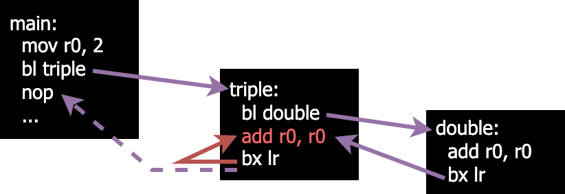
We can see that things are going okay (although we have an incorrect value after the add line in triple)
until we try to return from triple. Instead of ending up at the nop in main we instead return to the
add line in triple.
If you thought that this would happen then congratulations! you’re absolutely right. The
reason for this is that we overwrote the value of our link register when we
called double.
When we call bl, we save the address of the instruction following it into the lr register. This poses
an issue when we want to have nested functions (functions that call other functions) because we lose the address
to return to when we’re finished. We can get around this by utilising the stack.
The Stack#
You may already have a good understanding of what the stack is and how it works, especially if you completed the “Stack and Function Calls” extension in Assignment 1. Even if this is the case we recommend reading this section to ensure you understand how the stack works on your Microbit specifically.
By convention: the value of the sp (stack pointer) is an address in the SRAM region of the
address space (like with the .data section). Basically, it’s memory you can use to get things done and as
long as you maintain good stack practice then you won’t have to worry about interfering with or breaking
other areas of your program.
Common things that get stored on the stack include:
- “saving” values in registers which would otherwise be overwritten (e.g.
lr) - passing parameters/returning values between function calls
- temporary / local variables
It’s called the stack because (in general) it’s used like a first-in-last-out (FILO) stack “data structure” with two main operations: push a value on to the stack, and pop a value off the stack.
Stack Pointer in Memory#
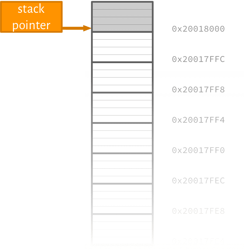
More About the Stack Pointer#
- the value (remember, it’s a memory address) in
spchanges as your program runs spcan either point to the last “used” address used (full stack) or the first “unused” one (empty stack)- you (usually) don’t care about the absolute
spaddress, because you use it primarily for offset (or relative) addressing - stack can “grow” up (ascending stack) or down (descending stack)
- in ARM Cortex-M (e.g., your microbit) the convention is to use a full descending
stack starting at the highest address in the address space which points to actual RAM1.
Using the Stack#
So how do we actually use the stack? Well we can treat sp just like any other register containing
a memory address.
Storing
@ Put a value in r2 that we want to store on the stack
mov r2, 0xABC

@ The following are all equivalent for storing r2 on the (full descending) stack.

@ Pre-offset based (expanded)
sub sp, sp, 4     @ decrease sp by 4 to point to the first "empty" spot
str r2, [sp]      @ store r2 at new sp


@ Pre-offset based
str r2, [sp, -4]! @ sp := sp - 4, then store r2 at new sp value
                  @ (the ! makes the offset persist in the register
                  @ contained in the [ ])

@ Dedicated instruction
push {r2}
Loading
@ Assume that the sp is currently pointing to an address that
@ contains a value we want to load into r3

@ The following sections are all equivalent for loading a value
@ into r3 and "removing" it from the stack.

@ Post-offset based (expanded)
ldr r3, [sp]      @ store the value from sp into r3
add sp, sp, 4     @ increase sp by 4 to remove value we just loaded

@ Post-offset based
ldr r3, [sp], 4   @ load value from sp into r3, then sp := sp + 4

@ Dedicated instruction
pop {r3}
You should use the offset based versions at first since it’s more clear what exactly you
are doing, but for later exercises you may want to use the push/pop versions.
All of the above options for loading “remove” the value from the stack, but what does that actually mean? Is the value unrecoverable?
Fixing Our Nested Function#
With our new knowledge of how the stack works, we can fix the issues that we identified previously:
- we were overwriting the
lr(link register) when we made our nested function call - we were losing our value needed to perform the final addition in
triple
double is a leaf function (doesn’t make any nested calls), so no modifications are needed for this
function.
.type double, %function
@ Doubles a given value
@ args:
@   r0: value
@ returns:
@   r0: value * 2
double:
  add r0, r0
  bx lr
.size double, .-double

.type triple, %function
@ Triples a given value
@ args:
@   r0: value
@ returns:
@   r0: value * 3
triple:
  str lr, [sp, -4]! @ Store the link register on the stack
  str r0, [sp, -4]! @ Store the value to triple on the stack
  bl double
  ldr r1, [sp], 4   @ Load the original value to triple into r1
  add r0, r1        @ Add the doubled value with the original value
  ldr lr, [sp], 4   @ Load the original link register value
  bx lr
.size triple, .-triple
These changes result in the following execution flow:
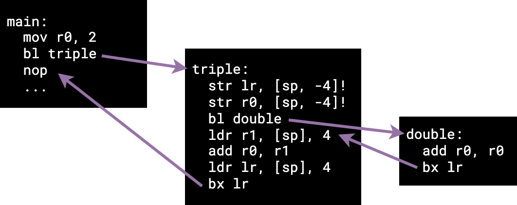
We can see now that by using the stack, we have been able to save the correct
return address (the nop in main) of our nested function triple.
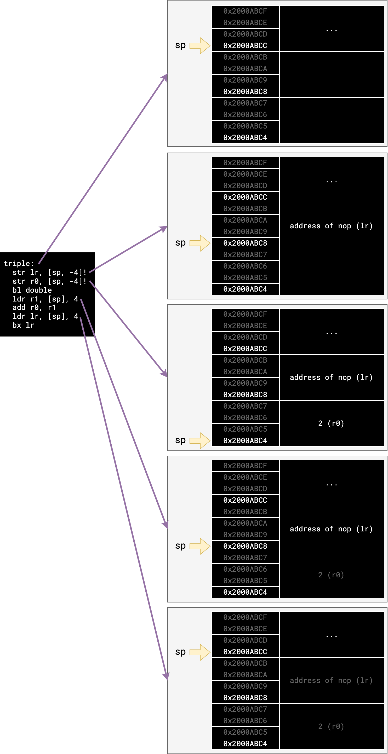
Here is a diagram of how the stack changes with the execution of triple
(where the first stack diagram is the stack view when triple is called, and the
following stack diagrams are the way the stack looks after executing the linked
instruction):
Task 3: Blink with Functions#
Now that we have our set and clear functions, we can revisit our blink function from the previous lab. Previously you would have:
- turned an LED on
- delayed for some amount of time
- turned an LED off
- delayed for some amount of time
- looped
Our aim is to extract this behaviour into a function to blink any LED for us using parameters.
In that lab, “turning on/off an LED” was as easy as setting a single row’s OUT value, but in general you need to be careful that this doesn’t also turn on LEDs in the same row, either by explicitly disabling those columns by clearing their DIR bit or setting their OUT bit. It worked out for us in the previous lab however because the other columns had 0 as their DIR bits by default and we did not set them.
We will create a function called blink_led which turns a single led in column 1
on, delays, then turns it off and delays.
Copy the following code into your main.S file:
.syntax unified
.global main

.type main, %function
main:
  nop
  @ add your instructions here
  @ you may want to add some code to set the DIR register here rather than in
  @ "blink_led" to avoid repetition

inf_loop:
  nop
  b inf_loop

.type blink_led, %function
@ blinks an LED in the left-most column.
@ args:
@   r0: bit index of the row to light up
blink_led:
  @ save link register, arguments on the stack

  @ call set_bit with correct arguments

  @ call delay with correct arguments

  @ call clear_bit with correct arguments

  @ call delay with correct arguments

  @ clean up stack, restore link register and return

  bx lr
.size blink_led, .-blink_led

.type delay, %function
@ args:
@  r0: delay amount
delay:
  subs r0, 1
  bmi delay_end
  b delay
delay_end:
  bx lr
.size delay, . - delay
Add your set_bit and clear_bit functions from the previous task into main.S
as well.
Complete the above code to the given spec. Then fill in main to use your
blink_led function to blink the top left LED, then the bottom left
LED, and repeat.
You may find it easier to set the pins for the rows and columns in the DIR
register once at the start of main and only modify the OUT register
inside blink_led.
Copy the code into tasks/task-3.S. Commit and push your changes with
the message “completed task 3”.
Task 4: Arrays as Arguments#
In this task you will write a simple function that iterates through the elements of an array containing 32-bit words and updates their values.
Copy the following code into main.S:
.syntax unified
.global main, update_array

.type main, %function
main:
  nop
  ldr r0, =array
  ldr r1, =array_len
  bl update_array

@ infinite catch loop
inf_loop:
  nop
  b inf_loop

.type update_array, %function
@ ... write a description of what the function does here ...
@ args:
@  r0: base address of array in memory
@  r1: number of elements in the array
update_array:
  nop
  @ ... write your "update_array" function here ...
  bx lr
.size update_array, . - update_array

.data
array:
.word 45, 3, 12, 88, 4
.set array_len, (. - array) / 4
The arguments to update_array will be the starting address of an array in
memory and the number of elements in the array (also referred to as the
length of the array). In task 1 you wrote a function to determine the size of
an array — the length is just the size of an array divided by the size of each
individual element (4 in this case).
Your update_array function will modify each element differently, depending on
whether it is even or odd.
- If the element is even, the element is divided by two.
- If the element is odd, the element is multiplied by three and then incremented.
Once you have updated every element of the array, the function should return.
There’s an easy way to determine whether a number is even. If the
least significant bit of a binary number is 0 then it is even (and divisible
by two). Similarly, a number is odd when the least significant bit is 1.
Think about why this is the case, and how you can use the tst instruction
(see the cheat sheet)
to determine whether an element is even or odd.
Write the update_array function to meet the above specification. Add some
arrays to the .data section in memory to and use them to test your code by
calling the update_array function with the correct arguments in main.
This function will require both loops and if/else statements. Start by focusing on how to iterate through each element of the array using a loop, then how to add an if/else check to modify the element depending on if it is even or odd.
This task will most likely require you to use more registers that the previous tasks. It is important that you take this opportunity to practice following the calling convention and use the stack to store any callee-save registers so that you can restore them when the function returns.
The callee-save registers are those listed on the
calling convention page —
r4 to r11.
Copy your work to the tasks/task-4.S file. Commit and push your work.
Task 5: Recursive Functions#
A recursive function is one which calls itself, usually passing different arguments. This is useful when a task can be broken down into doing a smaller version of the task several times, and then combining the results. If you have done COMP1100 you should be very familiar with this idea; if not, feel free to ask a tutor. Alternatively, let this jolly englishman walk you through it.
We will implement a recursive function fibonacci that takes one argument, n (say it’s passed in r0),
and returns the nth number in the Fibonacci sequence. In other words:
-
If
nequals0or1, return1(the first and second Fibonacci numbers; because we’re computer scientists, we’re indexing from 0.) -
Otherwise, since each number is the sum of the previous two numbers in the sequence, return
fibonacci (n-1) +
fibonacci (n-2)
. In other words, recursively callfibonacciwith the argumentsn-1andn-2, sum the results, and return that.
Since each recursive call is with an input that is strictly smaller than before, the recursive calls
will eventually stop when the input becomes 0 or 1 and the program will start backing out of
recursive calls again.
Again, you need to use the stack to not only store your old link registers but also the parameters you are passing into functions so the registers don’t interfere with each other.
Your code should be something like this:
.syntax unified
.global main, fibonacci

.type main, %function
main:
  nop

inf_loop:
  nop
  b inf_loop

.type fibonacci, %function
@ args:
@  r0: n, the index of Fibonacci sequence to calculate
@ returns:
@  r0: the nth value of the Fibonacci sequence
fibonacci:
  nop
  bx lr
.size fibonacci, . - fibonacci
Write a recursive function that calculates Fibonacci as described. Copy the code into tasks/task-5.S.
Commit and push your changes with the message “completed task 5”.
Discuss with your lab neighbour—what are the pros and cons of having recursive calls in a function? Hint: think about how each recursive call affects the stack.
Task 6: Blinking Columns#
This task will provide you with very little templating code — it is up to you to determine what helper functions you will need to implement on your own.
For this task you will need to write a function that builds on the work you did
for your blink_led function from Task 3. In that task you wrote a
function that alternated between two different LEDs in the same column. Here
instead you will set different LEDs on a per-column basis in a loop.
The function you write blink_columns should loop through each column
one-by-one and light up different LEDs pins in different rows. The specific
rows you should light up depends on the column you are “up to”:
- Rows 2 and 3 for Column 1.
- Rows 1 and 4 for Column 2.
- Rows 2 and 5 for Column 3.
- Rows 1 and 4 for Column 4.
- Rows 2 and 3 for Column 5.
Additionally, your blink_columns function should take in two arguments. The
first is an “on delay” — this is a number to pass to the delay function that
indicates how long the LEDs should be switched on within each column. The second
is the “off delay”, which is how long all the LEDs should be switched off before
moving onto the next column.
Write the blink_columns function to meet the above specification. You will
need to write your own helper functions to make this task easier. Ensure that
all functions you write adhere to the calling convention.
Write code in the main function to call your blink_columns function with
different values for the two delay arguments.
What do you see on the Microbit LED display when the two delay arguments are set to very low values?
Extension tasks
The following tasks are beneficial for you to complete to further practice the use of functions as well as general assembly coding, but are not necessary to complete; you may do them in your own time.
Extension (Task 7): Morse Code 1#
The following 3 tasks are an extension and application of everything you’ve already done so far in the lab, so if you don’t finish them in time, don’t stress. They exist here to better help you solidify your understanding of what you’ve learnt so far.
Morse code is a simple communication protocol which uses “dots” and “dashes” to represent the letters of the alphabet.
The dots and dashes can be represented in different ways—as dots or lines on a page, as short or long beeps coming out of a speaker, or hidden in a song on the radio to reach kidnap victims, or as short or long “blinks” of an LED on your microbit.
In this lab content the morse code will be represented visually using a sequence of .
(dot) and _ (dash) characters, but for this exercise, you’ll be sending
morse code signals by blinking an LED on your microbit in short (dot) and
long (dash) bursts. Here’s the full morse alphabet (courtesy of
Wikipedia).

The Task#
Your task is to use / modify the functions you wrote earlier in the lab to
write three new functions in your main.S file:
-
blink_dot, which blinks an led (or leds) for a short period of time (say0x400000cycles—we’ll call this the “dot length”) and then pauses (delays) for one dot length before returning -
blink_dash, which blinks the led for three times the dot and then pauses (delays) for one dot length before returning -
blink_space, which doesn’t blink an LED, but pauses (delays) for seven dot lengths before returning
Once you’ve written those functions, write a main loop which blinks out the
sequence ... _ _ _ on an endless repeat.
Copy the code into tasks/task-7.S then commit and push your changes to GitLab.
Extension (Task 8): Morse Code 2 - A Morse Data Structure#
Now it’s time for the actual morse code part. In morse code, each letter (also
called a codepoint) is encoded using up to five dots/dashes. For example,
the codepoint for the letter B has 4 dots/dashes: _... while the codepoint for
the letter E is just a single dot .. You could store this in memory in several
different ways, but one way to do it is to use a data structure which looks like
this:

Each “slot” in the data structure is one full word (32 bits/4 bytes), so the total size of the codepoint data structure is 4*6=24 bytes. The first word is an integer which gives the total number of dots/dashes in the codepoint, while the remaining 5 boxes contain either a 0 (for a dot) or a 1 (for a dash).
What will the address offsets for the different slots be? Remember that each box is one 32-bit word in size, but that memory addresses go up in bytes (8 bits = 1 byte).
Here are a couple of examples… codepoint B (_...):

and codepoint E (.)

In each case, the “end” slots in the data structure might be unused, e.g. if the codepoint only has 2 dots/dashes then the final 3 slots will be unused, and it doesn’t matter if they’re 0 or 1. These slots are coloured a darker grey in the diagrams. (If this inefficiency bums you out, you’ll get a chance to fix it in the Extra Tasks section after the main exercises.)
Your job for this task is to write a function which takes (as a parameter) the base address (i.e. the address of the first slot) of one of these morse data structures and “blinks out” the codepoint using an LED.
As a hint, here are the steps to follow:
-
pick any character from the morse code table in the previous task
-
store that character in memory (i.e. use the
.datasection) using the morse codepoint data structure shown in the pictures above -
write a
blink_codepointfunction which:- takes the base address of the data structure as an argument in
r0 - reads the “size” of the codepoint from the first slot
- using that size information, loops over the other slots to blink out the
dots/dashes for that codepoint (use the
blink_dotandblink_dashfunctions you wrote earlier) - when it’s finished all the dots/dashes for the codepoint, delays for 3x dot length (the gap between characters)
- takes the base address of the data structure as an argument in
Since the blink_codepoint function will call a bunch of other functions, make
sure you use the stack to keep track of values you care about. If your program’s
not working properly, make sure you’re not relying on something staying in r0
(or any of the scratch registers) between function calls!
Write a program which uses the morse data structure and your blink_codepoint
function to blink out the first character of your name on infinite repeat.
Copy the code into tasks/task-8.S then commit and push your changes to GitLab.
Extension (Task 9): Morse Code 3 - ASCII to Morse Conversion#
The final part of today’s lab is to bring it all together to write a program which takes an input string (i.e. a sequence of ASCII characters) and blinks out the morse code for that string.
To save you the trouble of writing out the full morse code alphabet, you can
copy-paste the following code into your editor. It also includes a place to
put the input string (using the .asciz directive).
.data
input_string:
.asciz "INPUT STRING"

@ to make sure our table starts on a word boundary
.align 2

@ Each entry in the table is 6 words long
@ - The first word is the number of dots and dashes for this entry
@ - The next 5 words are 0 for a dot, 1 for a dash, or padding
@   (value doesn't matter)
@
@ e.g., 'G' is dash-dash-dot. There are 2 extra words to pad the
@       entry size to 6 words
morse_table:
  .word 2, 0, 1, 0, 0, 0 @ A
  .word 4, 1, 0, 0, 0, 0 @ B
  .word 4, 1, 0, 1, 0, 0 @ C
  .word 3, 1, 0, 0, 0, 0 @ D
  .word 1, 0, 0, 0, 0, 0 @ E
  .word 4, 0, 0, 1, 0, 0 @ F
  .word 3, 1, 1, 0, 0, 0 @ G
  .word 4, 0, 0, 0, 0, 0 @ H
  .word 2, 0, 0, 0, 0, 0 @ I
  .word 4, 0, 1, 1, 1, 0 @ J
  .word 3, 1, 0, 1, 0, 0 @ K
  .word 4, 0, 1, 0, 0, 0 @ L
  .word 2, 1, 1, 0, 0, 0 @ M
  .word 2, 1, 0, 0, 0, 0 @ N
  .word 3, 1, 1, 1, 0, 0 @ O
  .word 4, 0, 1, 1, 0, 0 @ P
  .word 4, 1, 1, 0, 1, 0 @ Q
  .word 3, 0, 1, 0, 0, 0 @ R
  .word 3, 0, 0, 0, 0, 0 @ S
  .word 1, 1, 0, 0, 0, 0 @ T
  .word 3, 0, 0, 1, 0, 0 @ U
  .word 4, 0, 0, 0, 1, 0 @ V
  .word 3, 0, 1, 1, 0, 0 @ W
  .word 4, 1, 0, 0, 1, 0 @ X
  .word 4, 1, 0, 1, 1, 0 @ Y
  .word 4, 1, 1, 0, 0, 0 @ Z
The main addition you’ll need to make to your program to complete this exercise
is a morse_table_index function which takes a single
ASCII character as input, and returns the
base address of the corresponding codepoint data structure for that character
(which you can then pass to your blink_codepoint function).
For example, the letter P is ASCII code 80,
and the offset of the P codepoint data structure in the table above is 15 (P is
the 16th letter) times 24 (size of each codepoint data structure) equals 360 bytes.
So, your main program must:
- loop over the characters in the input string (
ldrbwill be useful here) - if the character is
0, you’re done - if the character is not
0:- calculate the address of the morse data structure for that character
- call the
blink_codepointfunction with that base address to blink out the character - jump back to the top of the loop and repeat for the next character
If you like, you can modify your program so that any non-capital letter (i.e.
ASCII value not between 65 and 90
inclusive) will get treated as a space (blink_space).
Write a program which blinks out your name in morse code.
Copy the code into tasks/task-9.S then commit and push your changes to GitLab.
Extra Tasks#
Morse Extensions#
There are many ways you can extend your morse program. Here are a few things to try (pick which ones interest you—you don’t have to do them in order):
- can you modify your program to accept both lowercase and uppercase ASCII input?
- the current
morse_tabledoesn’t include the numbers 0 to 9; can you modify your program to handle these as well? - can you remove the need for the number of dots/dashes in each table entry altogether?
- this is far from the most space-efficient way to store the morse codepoints, can you implement a better scheme?
LED Library#
Combine what you’ve learned over this and the previous lab to create some LED utility functions. How could you parameterize the functions to make them the most useful and reduce similar code?
-
The address space is the set of all valid addresses
So on a machine with 32-bit addresses (like your microbit) that’s \(2^{32} = 4294 967 296\) different addresses
So you can address about 4GB of memory (is that a lot?) ↩