Introduction
This lab contains the content for labs 10 and 11. It will cover some crucial skills and points for assignment 2 and introduce interrupts. Some of the exercises won’t hold your hand as much as previous. This is by design as they more directly relate to the assignment.
Before you take this lab, make sure you’ve completed labs 6 - 9.
Plug in your microbit and clone your fork of the lab template and let’s get started.
If you forked the repo before May 11th, then you may have got an outdated version of the library files. You can either do an upstream pull to fix this or simply copy and paste the content from the following files:
Assignment Tools
Interlude 1: Using Libraries#
Up to this point, all of your assembly code has been contained in one file, but that all changes now. We have provided 3 library files to you, which you are free to use as you would like.
If you want to make modifications to these files, I suggest you copy paste the functions into a new file and rewrite them as you need (remember to change the name so you don’t double define it), so that we don’t miss any work that you’re doing.
-
lib/util.S: A library containing some functions for basic bit-ops and other similar functionality that we don’t want to have to write out each time we need them. -
lib/symbols.S: A library containing a bunch of definitions of commonly used memory locations and offsets for the microbit. -
lib/led.S: A library for interacting with the LEDs on the microbit- relies on both
lib/symbols.Sandlib/util.S
- relies on both
You can use any of the functions / symbols in these files as you would anything in main.
This is because of the following lines:
.global set_bit
This tells the assembler that the set_bit label needs to be available globally, and as
such it makes it useable in other files. So I can look at the set_bit function preamble
in lib/util.S:
@ --parameters--
@ r0: base address
@ r1: offset
@ r2: bit index
and use it in src/main.S like so:
main:
  ldr r0, =ADR_P0
  ldr r1, =OFS_GPIO_OUT
  mov r2, 3
  bl set_bit
which will set (make = 1) bit 3 at ADR_P0 + OFS_GPIO_OUT.
But what are ADR_P0 and OFS_GPIO_OUT? Good question! This brings us on to the next
part of the library, lib/symbols.S. This library uses the .set
assembler directive
to create a bunch of useful human readable symbols that you can use around your
program.
Don’t be fooled, this is just assembler hacking, when we do:
.set ADR_P0,   0x50000000 @ Port 0

@ ...

main:
  ldr r0, =ADR_P0
All that is happening is that the assembler is doing a find and replace for ADR_P0 with
0x50000000. So really, ldr r0, =ADR_P0 just becomes ldr r0, =0x50000000 which is what
you have already been doing.
Have a read through the libraries and see if there is anything in there you might find particularly useful. If there is anything confusing, ask your tutor.
Interlude 2: Stack Instructions#
Up until this point, you should have been using ldr and str to interact with
the stack. This was by design, so that you might better understand what is
actually happening on the hardware level and how a stack works.
Hopefully that has actually sunk in, and we can now use the nice instructions for interacting with the stack
stmdb and ldmia#
These instructions are short for
store multiple, decrement before
load multiple, increment after
We use them because the microbit uses a negative stack. You can find them on the cheat sheet under negative stack.
The instructions work as follows:
@ A single register value
stmdb sp!, {r0}
@ ...
ldmia sp!, {r0}

@ A comma separated list of register values
stmdb sp!, {r0, r1, r2, lr}
@ ...
ldmia sp!, {r0, r1, r2, lr}

@ A range of register values (r4, r5, r6, r7)
stmdb sp!, {r4 - r7}
@ ...
ldmia sp!, {r4 - r7}

@ As a combination
@ eg: store r0, r1, r3, r4, r5, r6, r7, r8 and lr on the stack
stmdb sp!, {r0, r1, r3 - r8, lr}
@ ...
@ restore r0, r1, r3, r4, r5, r6, r7, r8 and lr from the stack
ldmia sp!, {r0, r1, r3 - r8, lr}
push and pop#
The easiest way of interacting with the stack is to use push and pop. These
instructions take a list of registers and puts their values on the stack. So
as long as you’re consitent with your ordering, both within the instructions
and where the instructions are, you won’t break the stack frame, yay!
The instructions work as follows:
@ A single register value
push {r0}
@ ...
pop {r0}

@ A comma separated list of register values
push {r0, r1, r2, lr}
@ ...
pop {r0, r1, r2, lr}

@ A range of register values (r4, r5, r6, r7)
push {r4 - r7}
@ ...
pop {r4 - r7}

@ As a combination
@ eg: store r0, r1, r3, r4, r5, r6, r7, r8 and lr on the stack
push {r0, r1, r3 - r8, lr}
@ ...
@ restore r0, r1, r3, r4, r5, r6, r7, r8 and lr from the stack
pop {r0, r1, r3 - r8, lr}
The difference between push / pop and stmdb / ldmia is that with the latter we can
use a different register as our stack pointer if we so desired. It is also possible
to not update the value of the stack pointer, by omitting the ! from the
instruction, not that you would often do that.
When using either stmdb and ldmia or push and pop, there are a few rules
you need to follow:
The registers listed must be in ascending order#
that means that
push {r0, r1}
@ ...
pop {r0, r1}
is valid, but
push {r1, r0}
@ ...
pop {r1, r0}
isn’t.
Now that isn’t to say it won’t compile, cause it will. But what you have written won’t be exactly the same as what is happening and you’ll see a warning like:
Warning: register range not in ascending order
So what happens when you do this is that the assembler will automatically correct your input to be in ascending order. So the stack frame might end up looking different than you expect.
How these instructions build the stack frame#
These instructions work by starting at the highest register id and working down from there, storing each value to the stack as it goes.
What that means is that as far as the stack frame looks, the following are equivalent
push {r0, r2, r11, lr}
@ ...
str lr, [sp, -4]!
str r11, [sp, -4]!
str r2, [sp, -4]!
str r0, [sp, -4]!
Mixing lengths#
While I definitely wouldn’t recommend it, you can mix and match the lengths of your
push and pops as long as you’re eventually consistent.
That is to say, you can do something like this:
push {r0, r1, r3}
@ ...
pop {r0}
pop {r1, r3}
and everything will be fine. However I think it makes the code less reasonable and harder
to debug. If you want to do something like the above, I’d suggest just matching up
the instruction lengths and having multiple push / pops:
push {r1, r3}
push {r0}
@ ...
pop {r0}
pop {r1, r3}
Mixing registers#
Another thing you can do is mix register destinations. This means that you can restore a value into a register that is different to the one that you stored it in. For example:
push {r0}
pop {r1}
is perfectly valid and will effectively copy the value from r0, to r1. Again I would
only do this sparingly as it can also make it harder to debug and line up your
stack instructions.
As an exercise, fill out the values of registers r0 - r5 after executing the following:
mov r0, 0xFF
mov r1, 0xEE
mov r2, 0xDD
mov r3, 0xCC
push {r0, r1, r2, r3}
pop {r2, r3, r4, r5}
Debug the code in your microbit to check if you were right.
Task 1: Scanning#
In lab 8, I asked you how you might go about lighting up the center 8 LEDs, with the central most LED off. If you didn’t figure it out then, we’re going to look at it now.
The answer is scanning. This is where a sequence of LED(s) are turned on and off so fast that, to the naked eye, they all appear on at the same time, despite this not actually being the case.
Here are a couple videos of the phenomenon happening on your microbit:
Here the programs are turning a single column of LEDs on at any one time, delaying, turning the column off, delaying for a small amount to let current dissipate, then turning on the next column (on repeat).
For demonstration purposes, the delay controlling the length of time a column is on for varies, so that you can see when the column is on for a significant amount of time that we can easily tell that only that column is on. However, as that delay decreases it becomes harder and harder to tell, until it just appears that they are all on at the same time.
In summary:
- Init the leds by calling the library function with
bl init_leds(look atlib/led.Sif you’re curious what this is doing) - Begin a display loop
- Turn on the first column (or row) of LEDs in the image using the library
function
write_column_pins(orwrite_row_pinsif you’re doing rows) (again checklib/led.Sto see what argument the function takes) - Delay for a length of time
- Turn off the first column (or row) of LEDs in the image using the same function as before
- Delay for a short length of time (to let current dissipate)
- Repeat steps 1 - 4 for the next column (or row) of LEDs in the image until all columns (or rows) have been displayed
- Begin the display loop again
- Turn on the first column (or row) of LEDs in the image using the library
function
Use the scanning phenomenon to draw the following image:
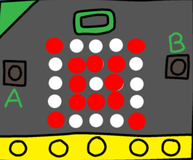
Copy the code into tasks/task-1.S. Commit and push your changes with
the message “completed task 1”.
Task 2: Displaying an Image From a Data Structure#
Now that you have an idea of how to display an arbitrary image, the next step in
generalization is to use a data structure to encode the image. This means that if
we wanted to change what is being displayed on the microbit, we only need to modify
the .data section of the program, the rest of the code doesn’t need to be modified.
Let’s create a data structure for drawing images. Now remember, there will definitely be better options for image data structures, but that’s kinda the point and something that you can explore in the assignment and tailor to your needs 😊
Back to the task, the data structure we’re going to use is a 5 word block to define how an image should look, column by column (if you’ve done row by row scanning then just rotate the data structure 90 degrees).
.data
image:
  .word 0b10001 @ Column 1
  .word 0b11010 @ Column 2
  .word 0b10101 @ Column 3
  .word 0b11111 @ Column 4
  .word 0b00101 @ Column 5
Let’s break down a line of this data structure:
.word 0b11010 @ Column 2
We have indicated that this is the information for column 2, however we can know this by convention in assuming that an image is defined by 5 words, with each word representing a single column in ascending order.
Then let’s look at the value: 0b11010 (0b just means this is binary)
This means that inside this column, a row is on if the bit at that index is 1, and off if
it is 0. So for this column we can see that:
| Binary Value | Row | LED State |
|---|---|---|
| 0 | 1 | Off |
| 1 | 2 | On |
| 0 | 3 | Off |
| 1 | 4 | On |
| 1 | 5 | On |
Where we have mapped the least significant bit to row 1, and then continued in ascending order for the 5 rows.
Coming back to our data structure from before:
.data
image:
  .word 0b10001 @ Column 1
  .word 0b11010 @ Column 2
  .word 0b10101 @ Column 3
  .word 0b11111 @ Column 4
  .word 0b00101 @ Column 5
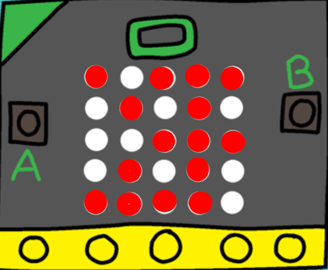
If we were to display the following image on the microbit, what would it look like?
Spoiler
It looks like this:
Update your scanning function to draw images based on the above data structure format. Test it on multiple different images using the same data structure format to make sure it works.
Copy the code into tasks/task-2.S. Commit and push your changes with
the message “completed task 2”.
If the following felt easy, great! Can you now create a moving image by adding extra
entries to your image data structure to create an array and display them on the microbit
as a loop?
Interrupts
Outline#
Before you continue with this part of the lab, make sure:
-
you understand control flow—what factors influence the order in which instructions get executed in your program
-
you have watched the lecture on the basics of interrupts
-
you’re able to browse around and understand new assembly code (e.g. provided in a library) with the help of the assembler documentation
In this section you will:
-
configure a timer interrupt to periodically “hijack” the control flow of your program
-
configure the GPIO pins connected to the buttons on your microbit so that pressing them triggers an interrupt
-
write an interrupt handler function to do something useful when you press the a button
-
use interrupt priorities to control what happens when different interrupts come in at the same time
Interrupts can take a bit of time to get your head around at first, so it’s really important that you work through this section in full and make sure you understand what’s going on. If you get stuck, make sure you read the lab content—there are lots of hints in there to help you out if you get stuck.
Introduction#
Discuss with your neighbour—what does it mean for your program to have a “main loop”? On your microbit, does your main loop have to do anything for the program to be useful?
So far, following the control flow through your program has been easy. In most
cases, the execution (which you can track through the pc register) just flows
from one assembly instruction (i.e. a line of assembly code) to the next.
Sometimes you jump around with branch instructions (e.g. b and bl), and in
certain cases you even make conditional branches using the condition flags in
the status register (e.g. beq, bgt or bmi).
From now, this all changes. You’re going to configure a timer interrupt which will periodically “interrupt” the flow of your program, execute a special interrupt handler function, and then return back to where your “main” program was executing. Then you’ll go further by showing how the microbit can handle multiple interrupts, each with their own handler function, and how each interrupt has a priority so that interrupts can interrupt one another. It sounds confusing… but it’s not, really. You’ll get the hang of it 😊
Task 3: Enabling the SysTick Timer#
A timer is a hardware component which holds a value (like a register) which counts down (or up) over time. Timers come in various shapes and sizes; some are simple and don’t have much potential for configuration, while others are extremely configurable, e.g. counting down to zero vs counting up from zero, counting at different rates, etc. Any given microcontroller can include many different timers, all with different names and configuration options, and multiple timers can be used simultaneously.
Your microbit has a timer called the SysTick timer, described in the ARMv7-M Reference Manual in Section B3.3. As with all things on your microbit, you configure the SysTick timer by reading and writing to special hardware registers. To configure and use the SysTick timer your program needs to:
-
enable the timer using the SysTick Control and Status Register (
SYST_CSR), (also set theCLKSOURCEbit to use the processor clock); -
set the SysTick Reload Value Register (
SYST_RVR)—this is the value which gets loaded into the register when it is “reloaded”, i.e. after it runs down to zero; -
read the current value of the timer register using the SysTick Current Value Register (
SYST_CVR).
For example, if the SysTick timer is enabled (in SYST_CSR) and the value of
SYST_RVR is 0x4000 then the timer will take 16384 cycles to count down to
zero. How long this takes in wall-clock time depends on the CPU frequency
(cycles per second) of the board.
To configure the SysTick timer you’ll need to use the load-twiddle-store pattern all over again. This time, the relevant information (addresses, offsets, bits) starts at Section B3.3.2 on page 677 of the ARMv7-M Reference Manual and includes the next couple of sections as well.
At this point in the course you have the tools to read the manual and figure it out for yourself (although don’t be afraid to ask your tutor for help). Here are a few things to be mindful of:
-
remember that these are memory-mapped registers, so e.g. to read the current value into a general-purpose CPU register (e.g.
r0) you need to use anldrinstruction with the appropriate memory address -
you can find the memory-mapped addresses for both of these registers in the table in Section B3.3.2
-
to enable the timer, you’ll need to set the enable bit in
SYST_CSRand also set the clock source to use the processor clock -
even though the timer will count down automatically (once tick per clock cycle) your program still needs to be running, so make sure you’ve got an infinite “run” loop in your program
-
the initial clock speed of your microbit when you first turn it on is 64MHz so keep that in mind when you’re setting the
SYST_RVRreload value
For this task, all you need to do is enable the SysTick timer, start it
running, and watch the values from the SYST_CVR.
Write an assembly program which configures the SysTick timer to count down from
4000000, and goes into a finished infinite loop when the timer reaches zero.
Copy your code to tasks/task-3.S and push it to gitlab.
When your code ends in the finished loop, how many times do you think SYST_CVR counted down to
0? Just once? Why might that not be the case?
Task 4: Configuring the Interrupt#
You may have noticed that there’s another bit in the SYST_CSR configuration
register which you didn’t set in the last task, but which looks interesting:
the TICKINT bit. The ARMv7-M Reference Manual says that this
particular bit:
indicates whether counting to 0 causes the status of the SysTick exception to change to pending
So what does this mean, exactly? Well, as discussed in lectures, an
interrupt/exception is “a signal to the processor emitted by hardware or
software indicating an event that needs immediate attention” (from
Wikipedia). If the TICKINT bit is
set in SYST_CSR, then the SysTick timer triggers an interrupt every time it
counts down to zero. Your CPU handles this interrupt by branching to an
interrupt handler which will
(hopefully) branch back when it’s finished. In words, when an interrupt comes in
then the CPU stops what it’s doing and branches somewhere else.
The ARM CPU in your microbit recognises many different types of interrupts. Some are triggered by timers, some are triggered by external peripherals (like the buttons), some are triggered by other chips or wires connected to the microbit.
All interrupts on your microbit have:
- an index (which is just a number for identifying the source of the interrupt)
- a priority
- an entry in the vector table, which is a region of the microbit’s memory where the addresses (i.e. the place to branch to) of the handler routine for each interrupt
You might be wondering—where does my code branch to when the interrupt comes
in? Well, that’s what the vector table is for. It’s a special part of the
memory address space (starting at 0x0) where the addresses of the
different interrupt handler functions are stored. Think of it like a bunch of
“jump-off points”—the code for handling the interrupt will be stored
somewhere else, the vector table just has the address of the starting point for
that code.
You can see your program’s vector table in the lib/startup.S file
starting at around line 60
.section .rodata.vtable
  .word _stack_end
  .word Reset_Handler
  .word NonMaskableInt_Handler
  .word HardFault_Handler
  .word MemManage_Handler
  .word BusFault_Handler
  .word UsageFault_Handler
  .word 0
  .word 0
  .word 0
  .word 0
  .word SVC_Handler
  .word DebugMon_Handler
  .word 0
  .word PendSV_Handler
  .word SysTick_Handler
  @
  @ more entries follow...
  @
What does it mean if there’s a 0 in a particular “slot” in the vector table?
Try and find the vector table for yourself in the startup file. Look for the
.section .rodata.vtable directive—can you see how it mirrors the table from Section
B1.5.2? You can see that there’s already a SysTick_Handler label in there in
the 16th slot in the vector table, but my “hot tip” to you is that the
SysTick_Handler function isn’t very interesting at the moment, it’s just
defined to be equal to the Default_Handler (which is just an infinite loop)
down at the bottom of the file.
Your job in this task is to build on the counter program you wrote in Task 3 and add a couple of things:
-
when you configure the timer, set the TICKINT bit as well
-
somewhere in your program, write a function (i.e. something which you can
blto, obeys calling convention and which does abx lrat the end) calledSysTick_Handler
We are setting up Systick_Handler as a function that we can bl to and which
does a bx lr at the end, however we won’t be doing the branching to this function.
Why is that?
If you set it up correctly, your Systick_Handler function will get called
every time the counter gets to zero.
Again, here are a couple of things to be careful of:
-
you’ll need to declare
SysTick_Handleras a label with.globalvisibility so that the address of yourSysTick_Handlerfunction will get used in the vector table insrc/startup.S(not the boring default one down the bottom of that file) -
similarly, make sure
SysTick_Handleris declared as a function with the usual.type SysTick_Handler, %function1 -
remember that the interrupt handler (in this case
SysTick_Handler) needs to be a function, and also to play nice and obey the AAPCS (otherwise it will mess with other parts of your program, you have been warned!)
Using the lib/led.S library provided, write a program which uses the
SysTick_Handler interrupt to toggle the an LED (or LEDs) on and off with a frequency of
1Hz (two toggles per second). Copy your code to tasks/task-4.S and push it to gitlab.
There are a lot of moving parts here, so here are some hints and things to think about:
-
to use the
lib/led.Slibrary, you have to call the (bl init_leds) function once at the start ofmain -
the board has a clock speed of 64MHz and the SYST_CVR value is reduced by 1 every clock cycle, however we only have 24 bits of space in the SYST_RVR (reload value register). What does this mean for the maximum length of time between interrupts?
-
it may be tempting to use registers to store global variables, however this is a recipe for disaster with interrupts (if you are unsure why this is the case, ask your neighbour or tutor), if you find that you are needing some kind of state between interrupts, then load and store to memory instead!
-
if you haven’t been using breakpoints, now is the time to do so. Put a breakpoint at the first instruction in your SysTick_Handler and run your code in debug mode, is it hitting the breakpoint? If so, step through your handler, is it doing what you expect?
Task 5: GPIO Interrupts#
Ok, so the SysTick_Handler looks after the SysTick timer interrupt, but what
about the other peripherals on your microbit? Is there a Button_Handler
for handling button presses? If not, where can you put your code to
be executed when a button is pressed?
The microbit includes a Nested Vectored Interrupt Controller (NVIC), a special bit of hardware which is responsible for watching the various bits of hardware (and software) which can trigger interrupts in your microbit.
A brief recap: remember that interrupts are a method of triggering an interruption to the sequence of assembly instructions being executed by the microbit. Configuring interrupts requires (at a minimum) enabling the interrupt and creating an interrupt handler—the function which gets called when the interrupt is triggered.
In this task we’re going to configure an interrupt that will be triggered
by changes on GPIO pins. The two buttons on your microbit are connected
directly to GPIO pins P0.14 (A) and P0.23 (B) as detailed in the
microbit V2 pinmap,
so if you can detect changes on these pins with an interrupt, you can run
specific code when the buttons are pushed. Finally you can use the buttons to
affect your program! This should feel pretty exciting.
Compared to the SysTick interrupt, there’s a slightly different process in configuring GPIO pins as sources of interrupts. This is because SysTick interrupt is one of the 16 “built-in” ARM Cortex interrupts—it’s not just something added by the microbit designers, it’s part of the ARM standard. The GPIO pins, on the other hand, aren’t part of a standard—each microcontroller manufacturer is free to include (or not) any number of GPIO pins on their board, and the way that they are wired into the CPU is up to them.
On your microbit, the GPIO pins are managed through the GPIO Tasks and Events Module (GPIOTE), this is described in Section 6.9 of the nRF52833 Product Specification. Out of “Tasks and Events”, events are things that can generate interrupts. Raising a GPIO-triggered interrupt is really a two-stage process (at least from the hardware’s perspective):
-
the GPIOTE module notices a change on the GPIO pins (e.g., a low-to-high voltage change) and raises an interrupt line into the NVIC
-
the NVIC deals with that interrupt, potentially saving the current register context to the stack and switching to the handler function (depending on whether the interrupt is currently enabled, whether any higher priority interrupts are already running, etc.)
So, to configure your microbit so that when you press a button an interrupt is triggered (which you can then write a handler for) you need to enable & configure the interrupt in both the GPIOTE and the NVIC. As with most things on your microbit, this is done by reading & writing the right bits in the right places to the various GPIOTE & NVIC configuration registers.
There are often more things to configure (i.e. GPIO pins) than there are bits in a 32-bit register—can you guess how the designers of the microbit get around this limitation?
Copy the code below to your main.S file.
.syntax unified
.global main
@ GPIOTE Constants
.set GPIOTE_EVENTS_IN0, 0x40006100
.set GPIOTE_INTENSET, 0x40006304
.set GPIOTE_CONFIG0, 0x40006510

@ NVIC Constants
.set NVIC_ISER0, 0xE000E100

.type main, %function
main:
  @ 0: init leds
  bl init_leds
  @ 1: Configure GPIOTE_CONFIG[0]
  @   Need to setup: mode, pin, port, polarity in the configuration
  @   register for GPIOTE[0]
  @ Section 6.9.4.8 in nRF52833 reference manual
  @   mode = 1 (event), pin = 14 and port = 0 (P0.14 = Button A),
  @   polarity = 1 (LoToHi)
  ldr r0, =GPIOTE_CONFIG0
  ldr r1, =(1 | 14 << 8 | 0 << 13 | 1 << 16) @ |
  str r1, [r0]

@ 2: Enable Interrupt for GPIOTE[0] (id = 6)
  @ S6.9.4.6 in nRF52833 reference manual
  ldr r0, =GPIOTE_INTENSET
  ldr r1, =0b1
  str r1, [r0]

@ 3: enable GPIOTE (interrupt #6 = NVIC_GPIOTE_ID) in NVIC_ISER0
  @ NVIC_ISER0: B3.4.4 in ARMv7-M Reference Manual
  ldr r0, =NVIC_ISER0
  ldr r1, =(1 << 6) @ set the 6th bit since NVIC_GPIOTE_ID = 6
  str r1, [r0]

loop:
  nop
  b loop
.size main, .-main


.global GPIOTE_IRQHandler
.type GPIOTE_IRQHandler, %function
GPIOTE_IRQHandler:
  @ setup a breakpoint here to check when the interrupt occurs.
  @ interrupt code goes here
  @ clear event
  ldr r0, =GPIOTE_EVENTS_IN0
  ldr r1, =0
  str r1, [r0]
  nop
  bx lr
.size GPIOTE_IRQHandler, .-GPIOTE_IRQHandler
In the code above, there are four setup steps:
-
Configure the GPIOTE channel 0 to to be in “event” mode, associate with GPIO pin 14 and port 0 (the pin and port of the A button), and to to listen for low-to-high voltage events (polarity = 1). Look in the nRF52833 specification section 6.9.4.8 to see how this register works. We’ve cleverly set up the config register in one line using some assembly directives.
-
Enable interrupts for events from GPTIOTE channel 0. This means just setting bit 0 in the GPIOTE “Interrupt Enable Set” register. Easy peasy. Note that if you want to disable interrupts from a GPIOTE channel you need to use the “Interrupt Enable Clear” register instead (
0x40006308). -
Enable the GPIOTE interrupt in the NVIC, its ID number is “6”. For this you need to set bit “6” in the NVIC’s Interrupt Set Enable Register (ISER; see B3.4.4 in the ARMv7-M Reference Manual). We use 6 as the id because the GPIOTE interrupt is at index 6 of the nrf52833 specific interrupts in the vector table.
-
implement a function called
GPIOTE_IRQHandlerand make sure you have the.global GPIOTE_IRQHandlerdirective.
So far so good, and this means that when your program is running, the if you
click button A, your microbit will end up executing the GPIOTE_IRQHandler.
One extra detail here is that you need to clear the record of the event that
triggered the interrupt. This means clearing the GPIOTE_EVENT_IN0 register.
If you don’t do this, the interrupt will happen over and over again!
This last section here (GPIOTE_EVENT_IN0) is basically us telling the CPU
that we have “handled” the interrupt and that it no longer needs to trigger it.
However, why didn’t we need to do this when it came to the Systick interrupt?
Use the above code to write a program where pressing button A toggles an LED on
and off, making sure you understand how the code works. Now, to test your
understanding, change the code so that it works with both button A and button B!
(Button B is on GPIO pin P0.23). Copy your code to tasks/task-3.S and push it to gitlab.
Task 6: Interrupt Priorities#
What happens when you are busy handling an interrupt and another interrupt happens? In this task you will construct such a scenario and see how interrupt priorities work.
Copy your Systick configuration code from tasks/task-4.S and use the following code as
the SysTick_Handler function:
.global SysTick_Handler
.type SysTick_Handler, %function
SysTick_Handler:
  mov r0, 0b01111
  bl write_column_pins
  mov r0, 0b10000
  bl write_row_pins
SysTick_Handler_infloop:
  nop
  b SysTick_Handler_infloop
.size SysTick_Handler, .-SysTick_Handler
This handler just turns on the bottom right LED and then goes into an infinite loop. The effect is that when the first SysTick interrupt happens, control flow will get stuck in this handler code.
This is actually a bad idea for writing an interrupt handler. Usually you want the interrupt handling to be quick (it’s supposed to interrupt the flow of execution, but not block it forever). But it’s useful to do it this way to see how interrupt priorities work.
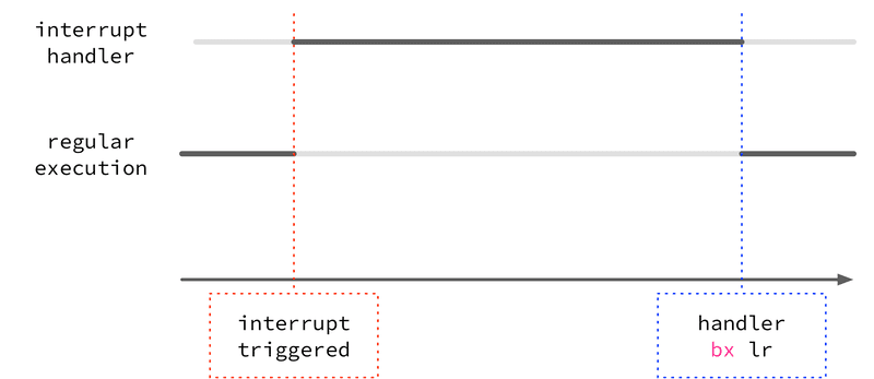
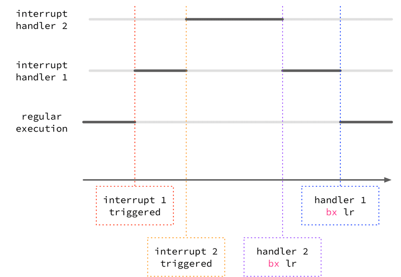
Now if you press button A when the LED is on, what happens?
Do you remember that the N in NVIC stands for nested? This means that the interrupts can happen inside of one another. Here’s a diagram to show what it might look like:
This isn’t the full story, though—the microbit doesn’t always “kick out” the
currently running interrupt for the new one, it depends on the priority. On the
microbit (as in life) some things are more important than others, and each
interrupt has a priority associated with it. On your microbit, this priority
is represented by a 4-bit number, with 0 being the highest priority and 15 being
the lowest. When an interrupt handler is running and a new interrupt is
triggered, it will only preempt (i.e., interrupt) the currently running interrupt
handler if the priority is higher (number is lower). If it’s the same or lower, that interrupt
handler will be run once the currently running one finishes (i.e. returns with
bx lr).
If your other LED from task 5 doesn’t turn on when you press button A and the bottom right LED is on, this means that the SysTick interrupt has the same or higher priority (i.e. a smaller number as the priority value) than the GPIOTE interrupt. To change the interrupt priority so that you can click the second LED on even when the first one is blinking (i.e. when the SysTick interrupt handler is running) you’ll need to lower the priority (give a higher number) to the SysTick interrupt.
Because the two interrupts (the SysTick timer interrupt and the GPIOTE interrupt) have some differences as mentioned earlier (one is part of the core ARM Cortex standard, one is a microbit-specific thing) you need to set their interrupt priorities in slightly different places:
-
for the SysTick interrupt, you can set the interrupt priority by writing bits 29-31 of the System Handler Priority Register 3 (
SHPR3, base address0xE000ED20) described in B3.2.12 of the ARM architecture reference manual -
for the GPIOTE interrupt, you can set the interrupt priority by writing bits 21-23 of the NVIC interrupt priority register (
NVIC_IPR1, base address=0xE000E404)
If you’re wondering how to figure out exactly which bits to set to control the priorities, that’s ok, it’s weird. Different Cortex-M4 CPUs have different numbers of priority bits available with up to a maximum of 8-bits which is the size of the fields in the control registers. On the microbit, we only have 3-bits available (7 different priority levels), and (weirdly) it’s the high three bits. So for any 8-bit priority field, you have to write bits 5-7. (How do we know? It’s in the nRF52833 manual section 4.1.2 “CPU and support module configuration”). You can read more about interrupt priorities here and in this article.
Modify the priority of your SysTick interrupt handler so that it does get
preempted by the GPIOTE handler and your second LED comes on when the first is on.
Copy your code to tasks/task-6.S and push it to gitlab.
Extra Tasks:#
More Buttons#
So far you have only worked with button A (GPIO P0.14) and B (GPIO P0.23)
to trigger the same logic. But your microbit also has four pads designed
for touch sensitive pressing (the central “logo”, and ring connectors 0, 1, and
2).
Can you do something more interesting with these other buttons? It could be something simple like toggling different LEDs based on what button is pressed, but the idea is to get started with more complicated interrupt arrangements.
Buttons A and B are triggered by a low-to-high event, and the touch sensors should be high-to-low.
You can use a different channel of the GPIOTE module for each button if you
like, but you will then need to sort out which “kind” of an interrupt (button
A, B, logo, or ring 0, 1, or 2) it is in the GPIOTE interrupt handler, you can
do that by checking which EVENT_IN[n] register has the lowest bit set, which
indicates that the event was triggered by the pin associated with that channel.
-
Again, this ensures that the thumb-mode (interworking) bits are set correctly and that the alignment is ok for the function to be used as an interrupt handler, and just generally handles the gory details about the ARMv7 standard for these things. ↩