This lab is a melting pot of a bunch of different exercises from the previous version of COMP2300 where we only focused on the microbit, and as such we took that content further. These exist here only to serve your curiosity and won’t be assessed directly, but if you have free time in Week 12 you are encouraged to take a look through. Some of the tasks here can help you with some of the advanced Assignment 2 extensions such as sound and networking.
Getting started
Files for these tasks are included in the Lab Pack 3 repo you cloned in Lab 9.
Part-0: Creating Sound
Task 1: Make some byte beats#
We’re going to make some sound with our microbits! This task is different
than LED tasks because we have provided a lot of code to help get sound
working on a microbit. Specifically we have a basic audio library (audio.S)
written by a previous COMP2300 tutor Benjamin Gray1.
You can find it here, save the file to your lib folder and remember to add,
commit and push it to gitlab.
Please note that the audio code uses the PWM0_IRQHandler, so changes to this configuration
or the interleaving of interrupts can affect the output of the audio code.
The idea of audio.S is to enable sample-by-sample audio playback on a
microbit. This is a very low level way of thinking about audio, but it’s
quite fun (as you will see in a minute). Digital sound is defined by “samples”,
that is a sequence of numbers over time that define how much a speaker cone
should be pulled or pushed to make a sound in the air that humans can hear. We
sometimes visualise digital sound waves like this:
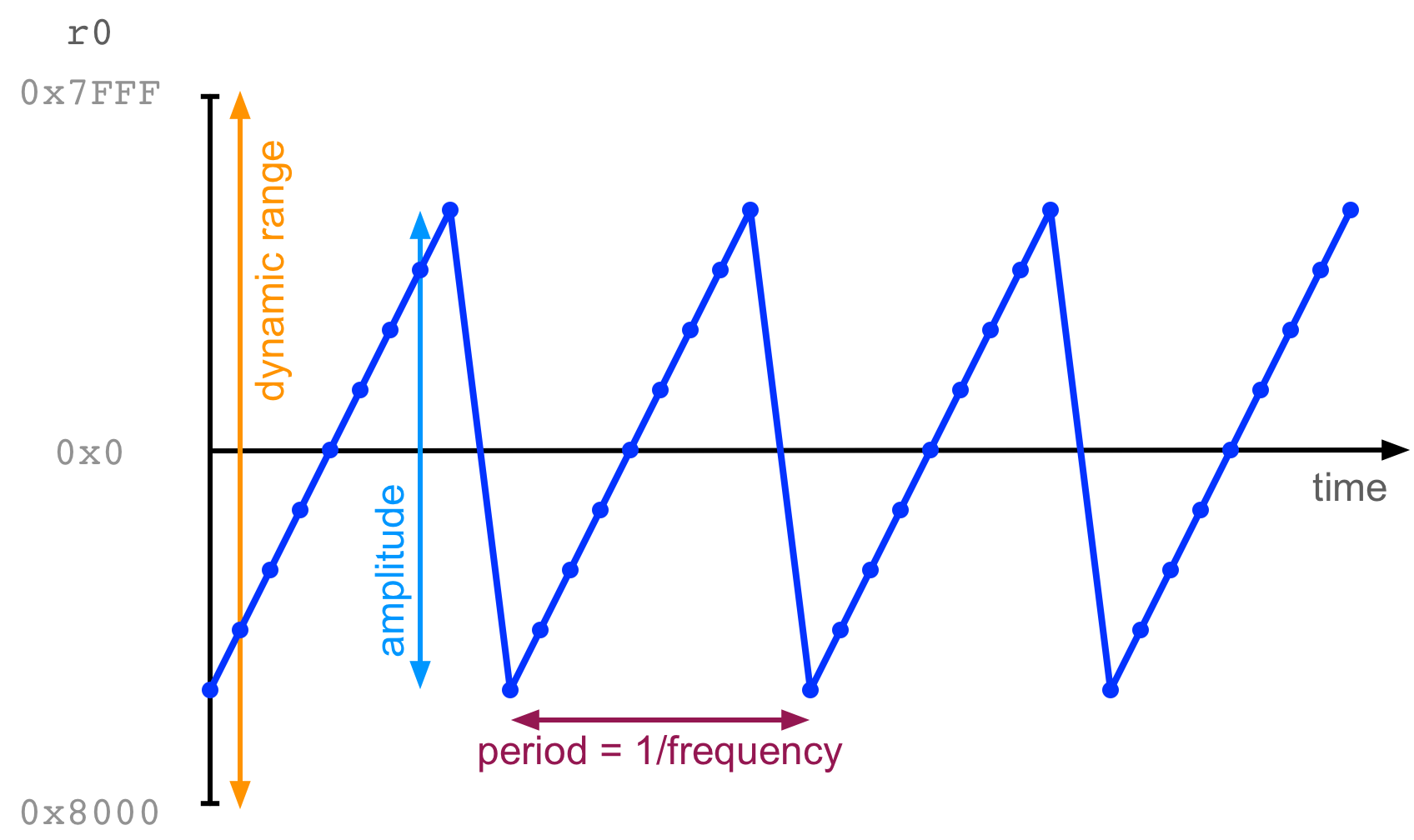
In that image, the little points each indicate a sample, that is a number
stored in r0. The x-axis is time, and the y-axis is the number in r0. Over
time, samples move in a repeating saw-tooth pattern, creating a sound. (We’re
going to do this on the microbit in a second).
You can open up audio.S and have a look at how it works (it’s well commented
and an excellent example of good assembly style). There are two functions
that are going to be important to get sound working:
-
audio_init: this function sets up sound on the microbit which basically means setting the speaker (GPIO P0.00) to output, enabling PWM (pulse width modulation) on this pin, and setting up some buffers and timers to ensure smooth audio. -
audio_play_sample: this function takesr0as an argument. It takes the lowest 8 bits ofr0and treats them as the next audio sample to play.
With these two functions, you can start creating some simple sound with your microbit! Let’s do it:
.syntax unified
.global main

.type main, %function
main:
  bl audio_init
  mov r5, #0
loop:
  add r5, #1 @ increment r5
  mov r0, r5
  push {r5}
  bl audio_play_sample
  pop {r5}
  b loop
.size main, .-main
Try compiling and uploading this program. It should play a steady tone from
your microbit speaker. The idea (as you might have guessed) is that r5 is
being incremented on each iteration through the loop. As it gets continually
larger, the output will form a sawtooth wave just like in the image above.
The example above shows a function audio_play_sample being
called. We know that r0 is treated as the argument of that function. If you
“build & debug” this code, stepping over the function call you might notice
that r0 has a different value at the other side of the function call. In
fact, the function audio_play_sample uses r0, r1, r2, and r3 for its
internal calculations and doesn’t attempt to save or restore these values
before returning. This behaviour is a normal part of the ARM calling convention
If you want to save the values of r0-3 when running a function (that you
didn’t write), you will need to save them somewhere (usually on the stack).
Making some byte beats#
Here’s the fun bit, if you do some mathematical transformations with r5 you
can create different kids of tones.
Try replacing mov r0, r5 in the program above with:
  lsr r0, r5, #8
  mul r0, r0, r5
This translates to (r0 = r5 * (r5 >> 8)) and it produces a much more interesting sound.
This concept of creating very small audio programs (usually in one line of C) is called “byte beat” and it was popularised by a demoscene programmer called Viznut in 2011.
Here’s another example:
  @ ((t >> 10) & 42) * t
  lsr r0, r5, #10
  and r0, #42
  mul r0, r0, r5
Both of these examples come from Viznut’s work.
Now it’s your turn to create some byte beats. Try experimenting with different
kinds of arithmetic transformations on the value in r5. You could start by
changing the immediates in the example above. What interesting sounds can you
create? Share your creations in your lab or post on Teams to get feedback from
your colleagues.
More Byte Beat Links#
Have a look through these links to find out more about bytebeat and the demoscene.
- Viznut: Algorithmic symphonies from one line of code – how and why?
- Discovering novel computer music techniques by exploring the space of short computer programs
- Bytebeat: Hacking Your Way to Music One Byte at the Time
- HTML5 Byte Beat Editor
Extra Tasks#
Two Byte Beats#
Our byte beats worked by manipulating one counting variable (r5) and sending
that output to the speaker. Can you think how you might be able to play back
two byte beats (based on different counting variables) at the same time?|
Consider that when you “mix” two sounds, you are simply adding the waveforms together.
Byte Beat Distortion#
“Distortion” in audio electronics is achieved by amplifying a signal past a “maximum” value in an electronic circuit (or a digital representation). How would you create distortion on one of your byte beat sounds?
Consider that “changing the volume” of a digital signal is achieved by
multiplying samples by a constant value. Don’t forget that in this case, on
the lowest 8-bits of r0 are used to create the sound.
Join a byte beat band#
Get some members of your lab and start a “byte beat band” with multiple microbeats. If that sound like fun, then maybe you should think about taking the “Laptop Ensemble” course at the ANU (COMP3710/6740). In that course, you’ll learn a lot more about computer music than we can teach you as an extra task in COMP2300 and you’ll work as a team with a group of similarly minded students.
Part-1: Using C
For this section, please use the lab-12-c folder.
Introduction#
In this section of the lab we’re going to look at writing programs for your microbit in a different programming language: C! C appeared in 1972 but is still popular today. Its style has been emulated in many modern programming languages such as C++, C# and Java, so if you have worked in any of those languages before, some parts of the syntax will seem quite familiar.
The reason we look at C is that is important as a “systems” programming language, and it is intertwined with the development of the Unix operating system (and later, the Linux kernel). C gives you some of the features of high-level programming (like functions, loops and control structures), but also some of the control of assembly such as direct manipulation of memory. In fact, many people say that C is “just one step above assembly”.
You’ll learn about a few of C’s language features and see how you can use it to accomplish some of the tasks that you already do in assembly (e.g., accessing a memory mapped register to turn on an LED). You might find that some parts of this are “easy”, it’s definitely easier to write a for loop in C than assembly! And other parts are a bit tricky since you’re used to manipulating registers and memory very directly in assembly.
Note that this is not a complete primer in C, there’s lots of details that are skipped, we’re just looking at a few features of the language that reflect the kind of programming we have done in assembly. If you want more info, we suggest reading the definitive book “The C Programming Language”, written by Brian Kernighan and Dennis Ritchie who designed C and were also involved in creating Unix. This book is so famous that it’s just called “K and R”, any computer scientist will know what that means.
While you’re doing these tasks you might find some of these links to be helpful:
Task 1: Functions Variables, and Disassembly#
Open up your main.c file for this lab, you’ll see that intead of main.S, it’s
called main.c! All through the course, our code has actually been assembled
by gcc, the GNU compiler, if the compiler sees a .S file, it just assembles
it, but if it sees a .c file, it compiles the C into machine instructions.
The file contains a simple main function:
int main(void)
{
  return 0;
}
You can see that the function syntax looks similar to Java, this function
doesn’t take an argument (void) but it does have a single return value of
type int.
Your task here is going to be to create a second function that adds three numbers together, and call it from the main function.
To do this, you’ll want to learn a bit about the types of variables available in C, so read the following sections.
Variable Types#
The C language needs you to declare the “type” of a variable before you can use it, this information lets the compiler use an appropriate amount of memory for storing your variable, you can also use qualifiers to let the compiler know if you want a variable to be signed or unsigned (finally!)
You’re probably familiar with declaring a type for a variable as follows:
int x = 5;        // Declare variable x with value 5
int x;            // Declare variable x without initialization - bad practice!
There are four basic types that you can use in C:
char(1 byte, often used to store a single ASCII character—hence the name—but it can also store numbers)int(4 bytes)float(a 4-byte IEEE-754 representation floating point number)double(an 8-byte IEEE-754 representation floating point number)
The four basic type qualifiers are unsigned, signed, short, and long.
You can combine these as follows:
short unsigned int = 23;
which creates a 2-byte variable (not 4), and specifies that it can contain unsigned numbers only (i.e., 0–65535).
Create a few variables in your main function and try compiling your program to see how it works.
Operators and Control Structures in C#
C supports most of the normal operators you would have experienced in other programming languages, a formal list is here. E.g.:
int a = 12;
a = a + 34;
a--;
++a;
(N.B.: what’s the difference between a++ and ++a?)
C also has typical control structures, e.g.:
if (a == 13) {
    b = 26000;
    a++;
}
You can read about C’s control structures here
Writing functions#
Functions in C have the following form:
<return-type> functionName( <parameter-list> )
{
    <statements>
    return <expression of type return-type>;
}
See C Syntax for more information.
Back to the task…#
So returning to you task, you have to:
- create a second function
- that adds three numbers
- and call it from your
mainfunction
Probably not so hard, but here’s the twist: you also have to use the
disassemble function command in VSCode to see the actual instructions that
the C compiler has used to implement your function! Use the debugger to step
through your program and notice that it automatically shifts to the disassembly
to step through each actual instruction.
With a partner or a small group, answer the following questions:
- how are local variables stored in your program?
- how are parameters passed from one function to another?
- how are return values handled?
- is C call-by-value or call-by-reference?
Add your code to the tasks/task-1.c file and push to gitlab. If you have any
questions about your function, discuss with your group and ask your tutor!
Task 2: Memory, pointers and the reference operators#
With assembly programming you have gotten used to the idea of moving memory addresses around to represent different variables in memory. You’ve had to just know whether a value in a register refers to a variable, or a memory address pointing to a variable.
Happily, C helps us to make this distinction precise by allowing to define pointers as a kind of type and to easily get anny variable’s memory address and to later retrieve the actual value at that address.
To declare a pointer you need to specify the type the pointer is supposed to
point to and then a star (*), e.g.: int *p declares a pointer called p to
an int (but we haven’t connected it anywhere yet).
To use pointers we have two operators that help us get memory addresses and the
values behind those addresses: & (reference) and * (dereference):
- If you have a variable
x, then&xis the address ofx. - If you have a pointer
p, then*pis the value pointed to byp.
Let’s look at an example in code:
int x = 102; // declare an int x with value 102
int *p = &x; // declare an int pointer (pointer to an int) and set to the address of x
*p = 99; // change the value of x to 99 (changing the memory that p points to!)
You could write this in pseudo-assembly as follows (assuming that x and p
are labels to somewhere in memory):
@ x = 102
ldr r0, =x @ get a memory address labelled x
mov r1, 102
str r1, [r0] @ set value at x to be 102

@ int *p = &x
ldr r0, =p @ get a memory address labelled p
ldr r1, =x @ get memory address labelled x
str r1, [r0] @ set value at p to be address of x (&x)

@ *p = 99
ldr r0, =p @ get the address of the pointer
ldr r1, [r0] @ get the value of the pointer
mov r2, 99
str r2, [r1] @ set value of memory pointed to by p to be 99
(PS: no guarantee that any compiler will produce anything like the above, this is just to help understand what’s going on!)
The * symbol causes confusion with pointers. * is used for three purposes
in C: to declare pointer types, dereferencing pointers, and regular old
multiplication. Confusing!
Now, a cool way to use pointers is to create functions with parameters
passed-by-reference. For example you might have a function that takes two
ints by value: int func(int a, int b) but you could change the types of the
parameters to be int * instead.
So here’s your task:
- Create a function called
squarethat takes one argument (by reference) and updates that value to be its square. Your function should havevoidas the return type (that is, it doesn’t return the new value, it just changes it in memory!)
Look at the dissassembly of your function, with a small group answer the following questions:
- how are the pointer operators implemented in assembly? (is it like the example above or completely different?)
- are there any advantages you can see to using pointers?
- what might go wrong if you used a lot of pointers in your code?
- do you think your experience with assembly helps you to understand pointers? why?
Add your pointer function to tasks/task-2.c and push to gitlab.
Task 3: Arrays and Structs#
In this task we’re going to create a few data structures in C. C doesn’t
support many kinds of data structures, really it just has the two that we
discussed in assembly: arrays and records (called a struct). Let’s learn
about them, create some in the main function and then look at the disassembly
to see how they work!
Arrays#
Creating an array in C might feel familar:
int a[10]; // create an array of 10 int-sized variables (not initialised)
a[3] = 23; // set the fourth element of a (a[3]) to 23.
Now we get to the fun bit. If a[0] is the first element of the array, then what is a? It’s actually the pointer to the first element! That is you can write:
int *p = &a[0]; // create a pointer to the first element of the array
int *q = a; // create a pointer to the first element of the array
and p and q will then have the same value.
The second fun bit is that you can use arithmetic with a pointer to access elements in the array. For example:
ais a pointer to the first array element (a[0])a + 1is a pointer to the 2nd element (a[1])a + 8is a pointer to the 9th element (a[8])
In fact, in C a[i] is literally the same thing as *(a + i). (Even K&R say that this is “surprising”, so expect it to take a second to sink in).
This is similar to doing offset loads and stores in assembly, but somewhat more convenient because C is keeping track of how much space in memory each array element is taking up (1 int, so 4 bytes) and adding that amount to the pointer each time. No more having to remember the size of elements! (What efficiency!)
Although you can use a + i to refer to the ith element of an array, you can’t set a. It’s not a variable.
Structures#
A struct in C is a lot like a record as we defined it earlier in the
semester, e.g., the following code defines the template of a structure called “student”:
struct student {
  int uid;
  float score;
  char firstname[20];
  char lastname[20];
};
Declaring structures works as follows:
struct student empty;
struct student full = {1234567, 77.6, "first", "last"};
In the case of the “empty” structure, the component variables will contain undefined data.
So how do you access the variables within structures? For a structure variable, you can use . to address different components, e.g., full.score = 90;. If you happen to have a pointer to a structure, you use a -> which will dereferennce the component in place, so for example:
struct student *stu_ptr = &full;
stu_ptr->score = 43;
Remember that -> gets the actual value of a pointer-to-a-structure’s component, not a pointer to that component. That is: stu_ptr->score is the same as (*stu_ptr).score.
Make some arrays and structs#
Your task here is to:
- Create a “cheating” function that takes a reference to a
studentstructure, and changes its score to 110, but also changes the first character oflastnameto “X”.
Use the disassembler to figure out how the structures and and arrays are stored in memory. Try out some different ways of declaring structures and arrays. Discuss with your group:
- Are they stored differently if they are a local variable (of a funtion) vs a global variable?
- How similar are structures and arrays to your implementations in assembly?
Add your structure experiments to tasks/task-3.c and push to gitlab.
Task 4: Blink an LED in C#
Your final task is to repeat the “blinky” lab, but this time in C!
All throughout this course, we have been preoccupied with adjusting values in memory-mapped hardware registers. For instance, to turn on an LED, we had to set the direction of the column and row registers to OUT, then set the output of the row to HIGH.
Now that we know about pointers in C, we can actually do these kinds of
operations quickly and easily. For example, to set row 1 (P0.21) to OUT, we
can do the following:
volatile int *GPIO_P0_DIR = (int*) 0x50000514;
*GPIO_P0_DIR = *GPIO_P0_DIR | (0x1 << 21);
If you remember lab 8, this two line solution took us 6 assembly instructions to load the previous value of the direction register, adjust it, and store it back.
Before running off to translate all of your 2300 code to C, consider a few details:
- The pointer is declared as a
volatile int. The volatile keyword tells the compiler that the value being pointed to may change without being modified by our program. It is usually a good idea to use the volatile keyword when operating on peripherals. - We have used C’s bitwise or
|and left shift<<operators to construct the updated value for the register.
Now you have all the tools you need to turn on an LED with C! Go do it! It should only take a few more lines.
If you have forgotten the memory addresses needed, go back to the blinky lab..
When your code is working, look at the dissassembly again and discuss with your group:
- How do you feel about setting hardware registeres in “high level” C?
- Do you miss the raw power of assembly? Or does this make you yearn for the relative safety of C syntax?
- How would you implement an LED library in C? Is there anything you could do easily here that would be hard in assembly?
- How would you go about implementing a
SysTickHandlerand making a timed blinking LED in C? Have we taught you enough that it is possible? - How would you implement a one-byte-offset load in C? As in the assembly
instruction
ldr r1, [r0, 1]? Is it possible? Is it wrong?
Add your blinky code to tasks/task-4.c and push to gitlab.
Check the CI for each task you have pushed to make sure everything is compiling and working correctly!
Extra Tasks#
There’s a lot of extra tasks this time, remember that these are just for your learning, not for marks.
Extra Functions#
This task is to discover how to call functions that have lots of arguments, or complex arguments. Write something that you think will work, then check what the compiler has done with the disassembler. If you follow the calling convention, this exercise should be fairly easy. Do the following:
- In assembly, write a function
five_funthat takes 5 integers as arguments, and sums them. Call this function frommain. - In C, write a similar function with many integer arguments. Call this
function from
mainin your main.S file. - Write a C function that increments every number in an array by 1. Define an
array in main.S, and call it from
main. Don’t forget to.globalyour assembly file’s array. - Write an assembly function that decrements every number in an array by 1.
Define an array in
main.c, and call your function fromc_main.
Don’t forget about the length of your arrays for task 3 and 4! These tasks are more challenging than the first two.
Pass by Reference / Pass by Copy#
Passing by Reference or Copy are two distinct methods of providing arguments to functions. Pass by copy is the default behaviour in C - When calling a function, a copy of the value of each argument is made. These copies are stored as a local variable in the function’s stack frame. Changing these local variables within the function does not modify the value of the original variable passed as an argument.
Pass by reference, on the other hand, does imply that the original function arguments are modified. The reference, or pointer, to the argument can be used to directly operate on the argument in memory. Such functions can modify variables without returning anything - the function is said to have “side effects”.
Using either the student data structure or your own, your task is to write two functions:
- a function that modifies a struct using pass by copy, and returns the modified struct
- a function that modifies a struct using pass by reference, with no return value
Your function signatures should look something like this:
struct somestruct pass_by_copy(struct somestruct x);
void pass_by_ref(struct somestruct *x_ptr);
Don’t worry about doing anything too fancy - just increment an item or add two items together. Once you have written your function, look in the disassembler and answer these questions:
- Your struct is probably a bit larger than what can fit in 4 registers. Where is the rest of the struct going for the pass by copy function?
- For completeness, identify how the arguments are passed in the pass by reference function.
- Consider the number of instructions used in each function. Which method do you think is more efficient?
- Can you think of a situation where you would have to use pass by copy?
Deep vs Shallow copy#
While on the subject of passing by copy and reference, we will touch on another subject - Copy depth. Essentially, shallow copy is when the reference to some item is copied, whilst deep copy is when the contents of the item are copied. Inadvertent shallow copy can be a big problem in other languages; it’s also possible in C when working with pointers. Consider the following code snippets:
int array1[] = {1,2,3,4,5};
int array2[] = {6,7,8,9,0};
int *a1_ptr = &array1;
int *a2_ptr = &array2;
a2_ptr = a1_ptr;
int array1[] = {1,2,3,4,5};
int array2[] = {6,7,8,9,0};
for (int i=0;i<sizeof(array1)/sizeof(int);i++){
  array2[i] = array1[i];
}
Note that a2_ptr now points to the same array in memory as a1_ptr - this situation is called pointer aliasing, as multiple symbolic names are refering to the same location in memory.
In the examples above, there is another potential aliasing situation. What do you think might happen if you tried to access array1[5]? This is out of the bounds of array1! C doesn’t have any kind of bounds checking, so what value will you get?
Linked Lists (and other such data structures)#
You may be familiar with list and string types from other programming languages. These types often allow you to append more data to the end, unlike C’s fixed size arrays. These data types work by having a link from each element to the next. Appending to a linked list is as simple as creating a new element, and updating the last element of the list with a link to the new element. A linked list can be implemented in C like so:
struct ll{
  int value;
  struct ll *next;
};

struct ll third = {3,0};
struct ll second = {2,&third};
struct ll first = {1,&second};

int sum_ll(struct ll list);
complete the sum_ll function which sums all of the elements of a linked list. Note that the pointer for the last element of the list is 0. Once your function is done, add a fourth element to the linked list and make sure your function still behaves properly.
FizzBuzz with a Twist#
The standard FizzBuzz function generally takes an int input m and, for each
int n from 0 to m, prints n followed by one of the following:
"Fizz"ifnis divisible by 3"Buzz"ifnis divisible by 5"FizzBuzz"ifnis divisible by both 3 and 5
Your output should look something like this:
0
1
2
3 Fizz
4
5 Buzz
6 Fizz
7
8
9 Fizz
10 Buzz

...

14
15 FizzBuzz
16

...
up to the given value of m.
Unfortunately, we don’t have the luxury of a big standard library and a console
to which we can print output. Your task is to write a C function
NextFizzBuzz that takes an int as input and finds the next FizzBuzz
number—the next number divisible by 3 and 5. Call this function from your
main.S file to test for the correct output.
Part-2: Networking
For the rest of the tasks, use the lab-12 folder.
To complete this section, you’ll need some way to wire the edge connectors of the microbit together. The easiest way is croc clip wires, but otheroptions also exist.
Outline#
Before you start this section, make sure:
- you have completed the interrupt lab and understand how signals (i.e. voltage changes) on your GPIO pins can trigger interrupts
In this part of the lab you will:
-
configure the GPIO pins on your board for both input and output
-
connect the microbit rings to one another with physical wires
-
configure and write interrupt handlers to do things when stuff happens on these wires
-
connect your microbit to another microbit to demonstrate intra-microbit communication
-
simulate a multi-microbit setup where you connect the two sides of your microbit to each other with wires and send packet data across the wires turn on LEDs
Introduction#
In this part you’ll take a deeper dive into the GPIO & interrupt capability on your microbit to send messages from one microbit to another. As you know, the GP in GPIO stands for General Purpose, which means that each pin (the barcode-like little gold-coloured bits of metal in rows along the bottom of your microbit) can be used for either input or output. The mode (input mode, output mode) of a given pin is configured by writing certain bits to the GPIO configuration registers.
You’ll extend your knowledge of GPIO inputs, timers, and interrupts from lab 10 to change the GPIO output of a pin over time to represent a message, and then to sense and decode that message on another pin.
This part has some more gaps in the instructions, so make sure you ask your tutors if you get stuck. If you are having trouble, read the interrupt classic gotchas section where you can check off some typical problems with enabling interrupts.
In this part, you’ll be working on sending signals to and from GPIO pins by connecting these pins using clip wires. To start off, think about: in the context of GPIO pins, what is a signal? Is there a difference between a signal which comes internally through the microbit (e.g. the buttons on your board and the signal which comes in through an external wire?)
Task 1: Blink-Over-The-Wire With Polling#
This first task is going to seem like revision of the interrupts lab where you used SysTick to blink an LED, however this time you will use SysTick to send a signal across a wire to toggle the LED.
The good news is that you already have all the knowledge needed to make this work from your previous labs. It’s just a matter of stitching all the pieces together!
First, connect a jumper wire from Ring0 to Ring2
on your microbit, like so:
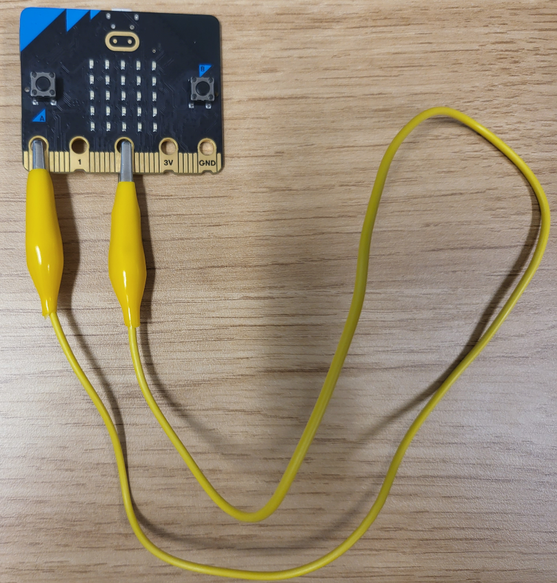
Now, using SysTick, you’re going to send a signal from Ring0 to Ring2
to turn an LED on and off. Here’s an outline of what your code should do to complete this task:
- Configure
Ring0(P0.02) as an output - Configure
Ring2(P0.04) as an input- This isn’t just setting the pin as an input, you also need to configure GPIOTE
to enable updating the
INevent for this pin. Section 6.9.4.8 of the nRF52833 Product Specification can help with this. Specifically, we want to enable the event for Pin 4 on Port 0 (but not as an interrupt… yet).
- This isn’t just setting the pin as an input, you also need to configure GPIOTE
to enable updating the
- Configure
SysTickto interrupt at a constant rate - In the
SysTickhandler you should toggle the output state ofRing0 - In the
mainloop of the program, you should poll the state ofRing2and …- Turn an LED on if the signal is high (1)
- Turn the same LED off if the signal is low (0)
All of these steps are things you have done before in previous labs, so look back through your lab tasks if you need to find hints on how to accomplish these tasks. Note that we are using a polling strategy to respond to input data from the GPIO pin.
To check your task is working correctly: Make sure that when the clip wire is connected, your LED blinks, but when it is disconnected, the blinking stops.
Write a program which blinks an LED at a rate of 2 times per second
using the jumper wire by polling.
Copy your code to tasks/network-task-1.S and push it to gitlab.
Task 2: Blink-Over-The-Wire With Interrupts#
As discussed in lectures, polling the current value on the pin in a loop isn’t always the best way to respond to inputs because it makes it hard for your program to do other work simultaneously. Happily, there’s a better way! In this task, you’re going to configure the GPIO input pin to trigger an interrupt when the value changes.
Modify your code from task-1 so that Ring2 (P0.02) triggers an interrupt when
it detects a change on the line and sets the LED accordingly. Here’s an outline of what your program will have to do to accomplish this task:
- Configure
Ring0(P0.02) as an output - Configure
Ring2(P0.04) as an interrupt enabled input - Configure
SysTickto interrupt at a constant rate - In the
SysTickhandler you should toggle the output state ofRing0 - In the
GPIOTE_IRQHandleryou should read the state ofRing2and …- Turn an LED on if the signal is high (1)
- Turn the same LED off if the signal is low (0)
- Clear the interrupt pending bit
- Do nothing in the main loop (make sure your program loops endlessly in main)
Write a program which blinks an LED at a rate of 2 times per second
using the jumper wire with interrupts.
Copy your code to tasks/network-task-2.S and push it to gitlab.
Task 3: LED Coordinate Packet Over the Wire#
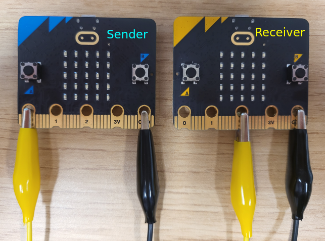
For this task your job is to create a “sender” program that sends a packet of data to a tutor’s microbit which will have the corresponding receiver code. You will connect your microbit to a tutor’s to check that your program is working.
Remote students: Unfortunately we can’t mail a tutor to you, so unless you can meet up with someone who has a microbit you’re not going to be able to test this exercise. But don’t fret! You can just skip the testing of this step and move on to task-4 where you’ll get to write both the sender and receiver on the same microbit.
In this task we’re going to connect microbits together!
Before looking at what you have to do to create the sender program we need to establish an agreed form of communication between your microbit and the tutor’s microbit. (Drum roll…) Introducing P2300-1W! A 1 way, 1 wire, serial protocol for controlling LEDs.
P2300-1W Features:
- 1000 bits per second bit rate (1 bit per millisecond)
- Packet based serial transmission
- Each 10 bit packet consists of:
- 1 start bit
- 1 byte of data
- 1 stop bit
- Each data block consists of:
- 4 bits indicating the LED row index (most significant 4 bits)
- 4 bits indicating the LED column index (least significant 4 bits)
- Data is transmitted in big endian (most significant bit first)
- Default high signal (line stays at 1 when no data is being transmitted)
So now that you understand the protocol, here’s an outline of what your code will need to do to complete this task:
- Configure
Ring0(P0.02) as an output - Set
Ring0high by default - Configure
SysTickso that it can successfully transmit a packet abiding by the P2300-1W protocol. - In the
SysTickhandler you should send a valid P2300-1W packet, this will be done over multipleSysTickinterrupts. This will encompass:- Sending a single start bit (indicated by a 1 -> 0 transition)
- Setting
Ring0to match the corresponding bit in the packet for each bit in the packet - Sending a single stop bit (indicated by setting
Ring0to 0 after the data has been sent) - Finalising the message by resetting
Ring0to high after the stop bit
- Do nothing in the main loop
To assist with this implementation its good to think about what information the sender needs to
keep track of to be able to accomplish its goal. As the message transmission will span multiple
SysTick interrupts, you will have to have variables stored in memory to keep track of what it
should be doing on a given interrupt.
Some hints are:
- Are you sending a message right now?
- What is the current message you are sending?
- Which bit are you up to in the current message?
If you think you’ve implemented this correctly, ask your tutor to bring you their board and a pair of jumper cables.
To test your implementation:
- Plug in your board
- Enter debug mode and wait on the main breakpoint
- Plug in the tutor’s board
- Wire the 2 GND pins together
- Connect your
Ring0to theirRing2 - Let your program run without any further breakpoints
If it worked correctly then the corresponding LED on the tutor’s board should light up.
Write a program which correctly implements the P2300-1W protocol as a sender and
turns on the LED at Row 3, Column 4.
Copy your code to tasks/network-task-3.S and push it to gitlab.
Task 4: Talking to Yourself#
You know what’s coming; let’s make a receiver!
This task assumes that you have implemented the sender from task 3 already, if you haven’t done so then go back to task 3.
In task 3 you implemented the sender for the P2300-1W protocol, for Task 4 you’re going to implement both the sender and the receiver on the same microbit.
For this task we will actually need two timers: one for sending (as in your
task 3 code) and a second one for receiving. You’ve already used SysTick for
the sender and unfortunately your microbit doesn’t have “SysTick2”, but it does
have five more timers called TIMER0-TIMER4. Again, unfortunately, these
timers work a little bit differently to SysTick. These timers count up
not down, they have a lot more configuration options available, and they
generate interrupts in a slightly different way. As these timers are part of
the nRF52833 microcontroller, not the Cortex-M4 CPU in your microbit, you have
to look in the MCU Reference 6.28 to learn about
them.
Something super important to note with the TIMERs, if they are enabled they will
continue to run even if you are “paused” at a break point or stepping through your
code. This means that if you have breakpoints mid-transmission then it is going to
mess with things unless you stop the timer beforehand and resume it afterwards.
This is not the case with SysTick as it runs from a different source.
To help get started we’ve provided some template code for using TIMER0, you can find it in the
lab-12/templates/task-4.S file.
It’s okay if you don’t understand everything that appears in the template code for the timer, the important parts are that you get familiar with the following functions and what they do:
init_TIMER0: configures necessary sections for the TIMER0 interrupt that we only want to do oncestart_TIMER0: starts the timer runningstop_TIMER0: stops the timer runningset_TIMER0: configures the duration between interrupts forTIMER0, it takes 1 argument inr0which is the amount of time in microseconds between interrupts (1 millisecond = 1000 microseconds)clear_TIMER0: resets the current count register for the timer
The code for init_TIMER0 is here for your refrence:
  @@ Set to timer mode
  ldr r0, =ADR_TIMER0
  ldr r1, =OFS_TIMER_MODE
  mov r2, 0
  str r2, [r0, r1]

  @ Set TIMER count value to 32bit mode
  ldr r0, =ADR_TIMER0
  ldr r1, =OFS_TIMER_BITMODE
  mov r2, 3
  str r2, [r0, r1]

  @ Set prescaler to 4 to get a 1 microsecond interrupt granularity
  ldr r0, =ADR_TIMER0
  ldr r1, =OFS_TIMER_PRESCALER
  mov r2, 4
  str r2, [r0, r1]

  @ Clear the internal timer count register
  ldr r0, =ADR_TIMER0
  ldr r1, =OFS_TIMER_TASKS_CLEAR
  mov r2, 1
  str r2, [r0, r1]

  @ Set compare event0 to trigger a clear of the timer value
  @ (this basically means when the timer counts up to the value in CC0 it resets the count to 0 automatically)
  ldr r0, =ADR_TIMER0
  ldr r1, =OFS_TIMER_SHORTS
  mov r2, 0
  bl set_bit

  @ Enable Interrupt on timer compare(0)
  ldr r0, =ADR_TIMER0
  ldr r1, =OFS_TIMER_ITENSET
  mov r2, (0b1 << 16)
  str r2, [r0, r1]

  @ Enable TIMER0 Interrupt (interrupt #8 = TIMER0_ID) in NVIC_ISER0
  @ NVIC_ISER0: B3.4.4 in ARMv7-M Reference Manual
  ldr r0, =ADR_NVIC
  ldr r1, =OFS_NVIC_ISER0
  mov r2, 8
  bl set_bit
To implement the receiver you also need to configure the GPIOTE handler to
listen to falling edges on Ring2 (P0.04). This is because a falling edge on this line indicates
that we are about to start receiving a message, at which point your program needs to enable the
TIMER0 interrupt and disable the GPIOTE interrupt.
Why is this the case? What would happen if we left the GPIOTE interrupt enabled? Could we still implement the receiver if it was left enabled? What if we never enabled the GPIOTE interrupt?
Here is a general idea of how the receiver should work:
- configure
TIMER0but don’t enable it - configure
GPIOTEand enable it to interrupt on falling edges (HiToLo) - when
GPIOTEdetects a falling edge onRing2it should:- put variables in place for the receiver to successfully receive the message
- configure the
TIMER0interrupt period and enable it - disable the
GPIOTEinterrupt - clear its pending bit
- when
TIMER0interrupts it should:- receive the current bit from
Ring2(P0.02) - append the bit to the current message (in the correct location)
- check if it has received a full message
- if it has received a full message it should:
- check the validity of the message
- turn off all LEDS and then turn the on the LED in the message
- disable the
TIMER0interrupt - clear the
GPIOTEpending (we don’t want it interrupting immediately if one was left pending) - enable the
GPIOTEinterrupt
- clear the
TIMER0pending bit
- receive the current bit from
Much like sending, receiving a message will also span multiple TIMER0 interrupts, so the receiver
will also need some variables in memory just like the sender does. Some hits are:
- Are you receiving a message right now?
- What is the current message you are receiving? (the in progress message)
- Which bit are you up to in the current message?
You are implementing the sender and receiver on the same microbit, however they should in theory be able to be split up and function across multiple boards like in task 3. This means having a clear distinction between which parts of your code are “sender” and “receiver”.
Generally speaking these are some things to take note of:
- the
mainfunction serves as the initial configuration for both sender and receiver - the
SysTickinterrupt acts as the sender, it should not be accessing any receiver variables, nor does it know anything about the current state of the LEDs orRing2 - the
TIMER0andGPIOTEinterrupts act as the receiver, they should not be accessing any of the sender variables, they also do not know about the state ofRing0 - the only shared memory that the sender and receiver should both have access to are read-only global variables
Write a program which correctly implements the P2300-1W protocol as both a sender and receiver and
turns on the LED at Row 4, Column 1.
Copy your code to tasks/network-task-4.S and push it to gitlab.
Extra Tasks:#
If you’ve gotten this far then we want to offer you a hearty COMP2300/6300/ENGN2219 congratulations! The tasks in this section of the lab are non-trivial, so very well done for getting to this stage.
Here’s some ideas for how to take this part of the lab further:
- send multiple messages to create a light show
- configurable data rate for messages
- variable message lengths
- different packet content
- get it to work with UART hardware
- implement SPI (synchronous serial)
Classic Interrupt Gotchas#
If you have trouble, here are a few questions to ask yourself:
- have you written the interrupt handler function, and is it globally visible?
- have you enabled the correct interrupt in the NVIC?
- have you configured the correct GPIO pin as an input pin?
- have you configured the correct GPIO pin to trigger an interrupt?
- have you configured the trigger for the interrupt (i.e. rising or falling edge or both)?
- does your interrupt handler function clear it’s pending register before it exits?
- do your interrupt handlers obey arm calling convention? (restore lr, save r4-r11, etc.)
Part-3: Operating Systems
This section of the lab work pulls together key concepts from our work on interrupts, operating systems, and CPU architecture. It’s basically a culmination of everything so far so it’s a good benchmark to see if you’ve understood everything.
Outline#
Before you attempt this part of the lab, make sure:
-
you understand how stacks work
-
you can write & enable an interrupt handler function
In this part of the lab you will:
-
explore (and exploit) the way the NVIC saves & restores register values when an interrupt handler is executed
-
construct the stack for a new process, then (manually) switch the stack pointer and watch the microbit execute that process
-
use multiple stacks to create your own multi-tasking operating system!
Introduction#
Today you’ll write your own operating system—you can call it yournameOS (feel free to insert your own name in there). At the beginning of this course the possibility of writing your own OS may have seemed pretty far away, but you’ve now got all the tools to write a (basic) multitasking OS. This part of the lab brings together all the things you’ve learned in this course, especially if you have a crack at some of the extension challenges.
Discuss with a colleague in your lab: how is it that your computer can do
heaps of things at once (check emails, have multiple programs and browser
tabs open, check for OS updates, idle on Steam, etc.)? Is there just a giant
main loop which does all those things one-at-a-time? Or is there some other
way to achieve this?
The basic idea of this part of the lab is this: instead of just using the default stack
(i.e. leaving the stack pointer sp pointing where it did at startup) you’ll
set up and use multiple different stacks. As you’ll see, a stack is all you
need to preserve the context for a process—an independent
sequence of execution—and switching between processes is as simple as
changing the stack pointer sp to point to a different process’s stack. The
interrupt hardware (i.e. the NVIC) even does a bunch of this work for you.
Task 1: anatomy of an interrupt handler stack frame#
In the first task it’s time to have a close look at how the current execution context is preserved on the stack when an interrupt is triggered.
Using a simple delay loop and the the usual helper functions in led.S,
modify your program so that after main it enters an infinite loop
which blinks one LED on and off at a frequency of about 1Hz. The exact
numbers aren’t important in this task, so pick some timing values which seem
about right to you.
When the ledblink loop is running, pause the execution using the debugger and
have a look at the various register values—lr, pc, sp r0-r3—you
should be starting to get a feel for the numbers you’ll see in each one. These
values make up the execution context—the “world” that the CPU sees when your
program (i.e., your ledblink loop) is running.
Then, enable and configure the SysTick timer to trigger an interrupt every
millisecond. There’s a big comment (starting at main.S line 12 in the
template repo) giving you some hints—you just need
to write the bits to the correct memory addresses. When figuring out the value
for the reload value register (SYST_RVR) remember that your board runs at 64MHz
on startup.
Once that’s working, you should be able to set and trigger a breakpoint in the
“do-nothing” SysTick_Handler at the bottom of main.s2. When
this breakpoint is triggered, use the memory view to poke around on the
stack—remember that sp points to the “top” of the stack, and the rest of the
stack is at higher memory addresses than sp (which will appear below the
sp memory cell on the screen in the Memory Browser because the addresses are
ordered from lower addresses at the top to higher addresses at the bottom). Can
you see any values which look similar to the values you saw when you were
looking around the execution context earlier?
Here’s what’s happening: when the SysTick interrupt is triggered, as well as
switching the currently-executing instruction to the SysTick_Handler
function, the NVIC also saves the context state onto the stack3,
so that the stack before & after the interrupt looks something like this
(obviously the actual values in memory will be different, but it’s the position
of each value on the stack that’s the important part):
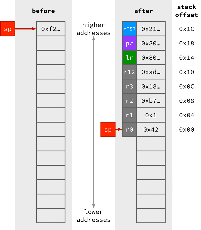
Don’t be fooled by the register names (e.g. lr or xpsr) alongside the values
in the stack. While the interrupt handler (in this case SysTick_Handler, but
it’s the same for all interrupts) is running, that context isn’t in the
registers, it’s “frozen” on the stack. When the handler returns (with bx lr,
as usual) this context is popped off the stack and back into the registers and
the CPU picks up where it left off before.
Discuss with your imaginary/real neighbour—how does the program know to do all this context save/restore stuff when it returns from the interrupt handler? Why doesn’t it just jump back to where it came from like a normal function?
You might have noticed a slightly weird value in the link register lr:
0xFFFFFFF9. You might have thought “that doesn’t look like any return value
I’ve seen before—they usually look like 0x8000cce or 0x80002a0”. Well, the
trick is that the value 0xFFFFFFF94 isn’t an regular
location/label in the code part of your program, it’s a special exception
return value. When the CPU sees this value in the target register in a bx
instruction then it does the whole “pop the values off the stack (including the
new pc) and execute from there” thing.
Commit & push your “empty SysTick handler” program to `tasks/os-task-1.S on GitLab. That’s all you need to do for Task 1, it’s just laying the groundwork for what’s to come.
Task 2: a handcrafted context switch#
Using a carefully-prepared stack, is it possible to call your ledblink
function without calling it directly using a bl instruction?
The answer is yes, and that’s what you’re going to do in Task 2. Disable (or just don’t enable) your SysTick interrupt—you won’t be needing it in this task.
Again, the key takeaway from Task 1 is that the context (the “world” of the current process’s execution) can be “frozen” on the stack, and then at any time you can “unfreeze” the process and send it on its way by popping those values off the stack and back into the registers.
In the last task, the frozen context was placed on the stack automatically by the NVIC before the interrupt handler function was called, but in this task you’re going to hand-craft your own context stack by writing the appropriate values into memory near the stack pointer.
To do this, you’ll need a chunk of microbit memory which isn’t being used for
anything else. There are several ways you could do this, but this time let’s
just pick a high-ish address (say, 0x20008000) in the RAM section of the
microbit’s address space.
You can get away with this since your program is the only thing running on the microbit, so if the other parts of your program leave that memory alone then you’ll be ok. On a multi-tasking OS, though, you have to share the memory space with other programs (some of which you didn’t write and you don’t know how they work) and so this assumption may not hold. There are a few ways to deal with this problem—can you think of how you might do it?
Once you’ve picked an address for your new stack pointer, you need to create the
stack frame. This can be anywhere in memory—there’s nothing special about
“stack memory”, it’s just a bunch of addresses that you read from & write to
with ldr and str (and friends). The memory address described above
(0x20008000) could be any old place where there’s a bit of RAM which you’re
not using for some other purpose.
To create stack frame, write a create_process function which:
-
loads the new stack pointer address (above) into
sp -
decrements the stack pointer by 32 bytes (8 registers, 4 bytes per register) to make “room” for the things you need to put on the stack
-
writes the correct values on the stack (see the picture above) to represent a running
ledblink-loop-
the status register (you can use the default value of
0x01000000) goes at an offset of28from your new stack pointer -
the program counter
pcshould point to the next instruction (which might be a label) to execute when the process is restored -
the link register
lrshould point to the instruction for the process to return to when it’s “done” (this doesn’t matter so much for the moment, because yourledblinkloop is infinite—it neverbx lrs anywhere) -
put whatever values you need into the slots for
r12and thenr3-r0—these are just the register values (arguments, basically) for yourledblinkprocess (think: do you need anything particular in here, or does it not matter for how yourledblinkloop runs?)
-
Once you’ve created the stack for your new process, write a switch_context
function to actually make the switch. This function takes one argument (the
new stack pointer) and does the opposite of step 3 above, loading the “context”
variables from the stack and putting them back into registers:
-
restore (i.e. put back) the flags into the
xpsrregister (since this is a special register you can’t justldrinto it, you have to load into a normal register liker0first and then use the “move to special register” instruction5msr apsr_nzcvq, r0) -
restore the rest of the registers except for
pc -
make sure the stack pointer
sppoints to the “new” top of the stack (i.e. after theledblinkcontext has been popped off) -
finally, set the
ledblinkprocess running by restoring thepc. Make sure that you have declaredledblinkas a function, e.g..type ledblink, %function ledblink: ...
Why can’t you restore pc with the rest of the registers in step 2?
Write a program which creates a ledblink stack frame “by hand” in
create_process and then switches to this new ledblink context using
switch_context. When it runs, your program should blink the LED. Copy your
program to tasks/os-task-2.S and commit & push your program to GitLab.
You may have noticed that the interrupt handling procedure only preserves
r0-r3, but not r4-r11. This won’t bite you if your processes don’t use
r4-r11, but how could you modify your switch_context function to also
preserve the state of those registers?
Task 3: writing a scheduler#
What’s the minimum amount of data (of any type) that you need to store to keep track of a process?
To turn what you’ve written so far into a fully-fledged
multitasking OS, all you need is a scheduler function which runs regularly (in
the SysTick_Handler) and makes the context switch as appropriate.
In this task you’ll put these pieces together to create version 1 of yournameOS. yournameOS is pretty basic as far as OSes go, it only supports two concurrent processes (for v1, at least). One of them blinks one LED, and the other one blinks a different LED (but with a different blink period—time between blinks).
The bookkeeping required for keeping track of these two pointers is just three words: two stack pointers, and a value for keeping track of which process is currently executing. You can the whole process table in the data section like this (note from the difference between the stack pointer values that the OS has a maximum stack size of about 4kB):
.data
process_table:
.word 0 @ index of currently-operating process
.word 0x20008000 @ stack pointer 1
.word 0x20007000 @ stack pointer 2
The only other tricky part is to combine the “automatic” context save/restore
functionality of the interrupt handler (as you saw in Task 1) with the
“manual” context save/restore behaviour of your switch_context function from
Task 2. You probably don’t even need a separate switch_context function
this time, you can just do it in the SysTick_Handler.
You can structure your program however you like, but here are a few bits of functionality you’ll need:
-
a
create_processfunction which initialises the stack (like you did in the previous task) for each process you want to run -
a
SysTick_Handler(make sure you re-enable the SysTick interrupt) which will
-
read the first entry in the process table to find out which process is currently executing
-
pick the other process and swap that stack pointer into the
spregister (but don’t change thepcyet!) -
update the
process_tableso that it shows the new process as executing -
trigger an interrupt return to get things moving again (make sure the handler function still exits with a
bxto the special value0xFFFFFFF9)
If you get stuck, remember to step through the program carefully to find out exactly what’s going wrong.
Write yournameOS version 1, including both a ledblink and an otherblink
processes which execute concurrently. Copy the code to tasks/os-task-3.S and
push it to gitlab.
The “return from interrupt” value for lr is usually 0xFFFFFFF9, but other
values are possible! If you look in section B1.5.8 (p.595) of the Architecture
Reference Manual, “Exception Return
Behaviour”, you’ll see that bits 0-3 in this exception return value can help
you switch between two SP values (the Cortex M4 can actually keep track of
two stacks for you: “main” and “process”), and put the CPU into “Handler” or
“Thread” mode. How would these features help you to upgrade yournameOS?
Extra Tasks: pimp your OS#

Once you’ve got your multi-process yournameOS up and running, there are several things you can try to add some polish for version 2. This task provides a few ideas—some of these are fairly simple additions to what you’ve got already, while others are quite advanced. Ask your tutor for help, read the manuals, and try to stretch yourself!
-
modify the scheduler to also save & restore the other registers (
r4-r11) on a context switch (as mentioned earlier) so that the processes are fully independent (currently, yournameOS v1 doesn’t preserve those registers, so if your processes are using them then the context switch will stuff things up) -
add support for an arbitrary number of processes (not just two)
-
add the ability for processes to sleep—to manually signal to the OS that they’re ready to be switched out
-
add the ability for processes to finish—to call their return address (in
lr) and exit -
add process priorities, and a more complex scheduler which takes these priorities into account
-
add the ability to press the joystick and manually trigger a context switch, but be careful—what happens if another interrupts occurs while the scheduler function is executing?
-
advanced: use the synchronization instructions
ldrexandstrexto add a critical section so that each process can share a resource (e.g. a memory location) without stepping on each other’s toes (for reference, look at the Asynchronism lecture slides & recordings) -
advanced: use thread privileges & the Memory Protection Unit (Section B3.5 in the ARM reference manual) to ensure that each process can only read & write to its own (independent) sub-region of the microbit’s memory.
-
Galaxy Brain: build a VGA connector & driver using the GPIO pins, then port Doom to the microbit
Whatever you made for your extension task, push it up to GitLab with a short note for future-you to remind yourself what you actually did. Don’t forget to also write a suitably self-congratulatory commit message. Well done, you!
Coda#
Folks, if you’re reading this, you’ve done it. You’re at the end of COMP2300/6300/ENGN2219 and you’ve completed all the lab material. I’m proud of you, and you should be proud of yourself: I bet you didn’t think you would be writing an OS when you starting adding registers in lab 2 (I hope that this lab was a sufficient final boss battle!).
-
Benjamin Gray is famous in COMP2300 circles for presenting a “discoboard emulator” as part of his tutor application which really saved the day in 2020 when many students ended up studying remotely. You’re probably familiar with it because it’s still included in the COMP2300 toolchain! ↩
-
If you need a refresher on this stuff, the interrupt lab is probably a good place to go. ↩
-
Section B1.5.6: Exception entry behavior on p587 of the ARM reference manual ↩
-
The full set of exception return values recognised by the microbit are shown in Table B1-9 on p596 of the ARM reference manual, but for the moment the one you’ll need is thread mode, main stack pointer which corresponds to the value
0xFFFFFFF9. ↩ -
The documentation for
msris in Section A7.7.82 on p323 of the ARMv7-Mreference manual, also see Table B5-2 on page 729 for the bit mask. Note that we also have anmrsinstruction, “Move to Register from Special register” (A7.7.81) that can copy bits from the APSR to a regular register. ↩